Underground engineering networks and equipment of the city. A complex of underground communications in a well-maintained city. Underground engineering communications: types and methods of laying What is underground communications
Department: "Engineering Geodesy".
abstract
On the topic: "Survey of underground communications".
Completed: student gr. MT-112
Rodin S.E.
Checked by: teacher
Andreev A.L.
Novosibirsk - 2001
INTRODUCTION
1. GENERAL INFORMATION ABOUT UNDERGROUND COMMUNICATIONS
2. EXECUTIVE SURVEY OF UNDERGROUND COMMUNICATIONS
2.1 ELEMENTS OF UNDERGROUND ENGINEERING COMMUNICATIONS TO BE SHOOTED
2.2. HORIZONTAL SHOOTING
2.3. VERTICAL SHOOTING
2.5. REGISTRATION OF THE EXECUTIVE DRAWING
3. SHOOTING OF EXISTING UNDERGROUND COMMUNICATIONS
3.1. GENERAL INFORMATION ABOUT THE ORGANIZATION AND CONTENT OF WORKS
3.2. OBJECTS AND SHOOTING TECHNIQUE
3.3. PREPARATORY WORK
3.4. RECOGNOSCIATION, INSPECTION AND LEVELING OF UNDERGROUND
COMMUNICATIONS
CONCLUSION
1. LICENSING OF GEODETIC WORKS
3. SAFETY IN THE PERFORMANCE OF ENGINEERING AND GEODETIC WORKS
BIBLIOGRAPHY
INTRODUCTION
With the growth of the improvement of cities and rural settlements, the technical level of modern industrial enterprises, the extraction of minerals, the saturation of their territories with various engineering communications is constantly growing. For the construction, design and operation of urban and industrial facilities, accurate data on the location in plan and in height of the entire complex of utilities are required, indicating their technical characteristics. This makes it necessary to carry out a large amount of engineering and geodetic work on surveying and drawing up plans for engineering communications.
Engineering communications are linear structures with technological devices on them, designed for the transportation of liquids, gases and the transmission of energy. They can be divided into two groups: underground and aboveground communications. As synonyms, they are also called engineering networks, and individual communications are called routes or gaskets.
Underground utilities consist of pipelines, cable lines and collectors.
The nature of the arrangement of the area where engineering communications are laid largely determines the features of their location and technological connections.
The territories of modern cities are saturated with a system of engineering communications, laid mainly below the surface of the earth. The location of urban utilities is determined by the size and configuration of the city's territory, the density and number of storeys of buildings, the level of development of the municipal services of the city (village).
The underground space of the city is most fully used within the territory of city streets. Here, the placement of underground utilities was carried out at predominantly minimal distances and a plan between individual gaskets, as well as between them and buildings, structures, roads, etc. Combined gaskets of underground utilities in collectors are widespread. Particularly dense distribution of communications is typical for central streets and squares.
In undeveloped areas, engineering communications are represented by separate trunk pipelines, overhead and underground power transmission and communication lines. In this case, the location and purpose of trunk communications in most cases is determined by identification posts.
Distinguish between executive filming of communications and filming of existing communications. Executive survey of utilities is carried out during and after the completion of construction, but before backfilling the trenches of underground utilities with earth.
Executive survey of engineering communications contains the following types of work:
preparatory;
creation of a planned-high-altitude survey geodetic network (justification):
plan-high-altitude survey of elements of engineering communications with measurements of structures on them.
In addition to the listed types of work during executive survey, the survey of existing utilities includes reconnaissance and inspection of utilities, as well as finding the location of hidden underground networks.
Upon completion of the field work, a complex of computational, graphic and map-making works is performed. Upon completion of the field and office work, a technical report (explanatory note) is drawn up, which contains the actual composition and scope of work, the technological features of the survey in a given area, the accuracy characteristics of the plans or executive drawings received.
1. GENERAL INFORMATION ABOUT UNDERGROUND COMMUNICATIONS
Underground utilities include such laying in the ground as pipelines, cable networks, collectors.
Pipelines - These are networks of water supply, sewerage, gas supply, heating, drainage, drainage, oil and gas pipelines and other gaskets designed for transporting various contents through pipes.
Cable networks transmit electricity. They differ in voltage and purpose: high voltage networks, electrified vehicles, street lighting; Weak toy networks (telephone, radio and television). Networks consist of cables laid at a depth of 1 m, transformer distribution cabinets.
Collectors are underground structures of a circular or rectangular cross-section of a relatively large size (from 1.8 to 3.0). Pipelines and cables for various purposes are laid in them simultaneously.
Water pipes provides drinking, household, veterinary and fire-fighting needs and consists of water supply stations and water supply networks. The water supply network is divided into main and distribution networks. The main network (pipe diameters 400 - 900 mm) provides whole areas with water, and the distribution network extending from it supplies water to houses and industrial enterprises. Pipes of this network have a diameter of 200 - 400 mm, inlets to houses - 50 mm. To regulate the operation of water supply networks, fittings are installed on them - valves, outlets, taps, etc. Wells are arranged for access to the fittings.
Sewerage ensures the removal of waste and contaminated water to treatment plants and further to the nearest water bodies. The sewerage network consists of cast iron and reinforced concrete pipes, inspection and drop wells, pumping stations for lowered parts of the building and other structures. Pipe diameters range from 150 to 400 mm.
Gutters drain rain and melt water, as well as conditionally baby water (from washing and watering streets). The drainage network consists of pipes, storm and drop wells, outlets into reservoirs and ravines. Downpipes of buildings are connected to the sinkholes. For the drainage network, asbestos-cement and reinforced concrete pipes with a diameter of up to 3.5 m are used.
Drainage used to collect groundwater. They consist of perforated concrete, ceramic, asbestos-cement pipes with a diameter of up to 200 mm.
Gas pipelines serve to transport gas. They are divided into main (diameter of steel pipes up to 1600 mm) and distribution. Gas pipelines run from stations and storage facilities to the development areas along the driveways. From them there are inputs to buildings and structures. The depth of laying from the surface of these networks is 0.8-1.2 m. On gas pipelines, shut-off valves, condensate traps, snuff pipes, pressure regulators, etc. are installed.
Heat supply networks provide residential, public and industrial buildings with heat and hot water. Heat supply is local (from individual boiler houses) and centralized (from combined heat and power plants), water and steam. Heat is supplied through direct supply pipes (temperature 120-150 ° C), returned to the source through return pipes (temperature 40-70 ° C). Heat supply networks consist of metal insulated pipes; valves placed in chambers; air and drain valves, condensation devices, expansion joints. The diameter of the pipes reaches 400 mm. They are laid underground in reinforced concrete Samples, and in case of mass dense building, pipes are led directly through the basements of buildings.
2. EXECUTIVE SURVEY OF UNDERGROUND COMMUNICATIONS
2.1. ELEMENTS OF UNDERGROUND ENGINEERING COMMUNICATIONS TO BE SHOOTED
Survey of underground utilities for drawing up executive drawings is carried out during their construction before backfilling trenches.
Regardless of the type of underground laying, wells, chambers and hatches, turning angles, points on straight sections along the axis of the underground network are removed at least 50 m later, places where the slopes of communications and pipe diameters change, places of connection and branch.
For each separate type of underground engineering communications, survey and determination are subject to:
through water supply and special technical pipelines (oil pipeline, fuel oil pipeline, oil pipeline, ash pipeline, etc.) - fire hydrants, valves, plungers, emergency outlets, water columns, stops at the angles of rotation, pipe diameters;
through sewerage (gravity and pressure), gutter and drainage - emergency outlets, gutter outlet heads, storm inlets, storm outlets, treatment facilities on gutters, stops at the turning angles of pressure sewers, dimensions of pumping station buildings, water supply and sewage pumping stations, pipe diameters;
on the heating network - expansion joints, valves, fixed supports, ground pavilions above the chambers, dimensions of buildings of central heating points (CHP), pipe diameters;
by gas pipeline - carpets, pressure regulators, gate valves, hydraulic gates, control tubes, compensators, plugs, dimensions of gas distribution stations (GDS), pipe diameters;
by electric cable - places of exits to the walls of buildings and supports, sections of blocks or channels in external dimensions, the number of channels, linear and tee couplings, transformers, dimensions of TP buildings;
on a low-current network - boxes, cabinets (indicating their type or standard), section of blocks or channels in external dimensions, number of channels, well sweeps;
for electrical protection against corrosion - contact devices, anode earthing switches (indicating their depth, location), electrical protective installations, electrical jumpers, protective grounding and drainage cables.
In this case, information and the number of gaskets, holes, about the material of pipes, wells, channels, about the pressure in gas and voltage in cable networks should be collected.
When underground engineering networks are located in blocks and tunnels, only one side of them is removed, while the other is applied according to the measurements. The outlets of underground networks and their structural elements should be connected to each other or tied to solid contours of the building by control measurements.
When shooting cables in bundles, measurements are made to the outermost cables from one side or the other.
All underground structures crossing or running parallel to the laying, opened by a trench are subject to mandatory survey. Simultaneously with the survey of the indicated elements of engineering communications, a survey of the current changes should be performed.
The width of the strip covered by the survey is set by the task, but must be at least 20 m from the axis of the strip.
2.2. HORIZONTAL SHOOTING
The planned position of all underground communications and related structures can be determined:
in the built-up area - from clear points ka feeding buildings, from points of the geodetic support network or points of survey justification;
on undeveloped territory - from points of survey substantiation or from points of a geodetic reference network;
in a through collector covered with earth - from the theodolite course laid inside the collector.
The position of underground utilities from clear points of capital development is determined by:

 linear serifs at least three (Fig. 1 and 2), their length is up to 20 m, in exceptional cases no more than the length of the measuring device (50 m). Angles between adjacent directions
the notches at the point to be determined must be at least 30 ° and not more than 120 °;
way of perpendiculars no more than 4 m in length (Fig. 3), longer perpendiculars are reinforced with serifs, in this case, serifs should be no more than 20 m;

 Fig. 4.
Figure: 3.
way of alignments along the continuation (alignment) of the contour of buildings, between clear points and
combining them with serifs. The permissible length of the alignment along the continuation should not exceed half of the original side, but not more than 60 m.
Shooting in various ways and their combination is shown in Fig. 4.
From points of the reference geodetic network and points of the survey network, the position of underground utilities is determined by linear intersections, perpendiculars, the polar method and the combined method, i.e., the scale in combination with the theodolite.
A polar survey is performed from geodetic reference grid points, survey grid points, or auxiliary points defined by three fixed point linear intersections.
In this case, the theodolite limb zero is oriented to a fixed point at least 50 m from the instrument.The length of the polar direction should not be more than 30 m when shooting at a scale of 1: 500, 40 m - at a scale of 1: 1000 and 60 m-scale 1:2000.
All linear measurements are made with steel tapes or tape measures. It is prohibited to measure lines with tape measures.
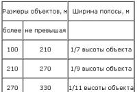
For wells with covers in the form of circles, the position of the center of the cover is determined, and for hatches and rectangular gratings, two corners are removed.
The distances to the contours should not exceed the values \u200b\u200bindicated in table. one
With a significant (more than 1 m) deepening of the removed elements of underground structures, the removal of the axis of underground communications to the surface is carried out using a plumb line attached to a pole or board laid across the trench.
The axes of underground utilities can be carried to the surface of the earth using a pole or rail.
When photographing wells and chambers, the internal and external dimensions of the structure, its structural elements are measured, the location of pipes and fittings is determined with reference to the sheer lime stick passing through the center of the well cover.
In this case, the following should be established: the purpose, design of wells, chambers, distribution cabinets and kiosks, the characteristics of the fittings available in them.
The measurement results are entered into the outline, where sketches are made in the plan in combination with the scheme of the theodolite traverse to be laid, the links to capital buildings, the linear dimensions of the structure, sections, etc. are shown.
All removed elements of the underground engineering network are sequentially numbered in the field outlines and magazines during the survey.
Surveying of underground utilities, laid by the shield boring method, is carried out from points of the geodetic support network and points of the survey network located on the earth's surface in the immediate vicinity of the tunnel route (no more than 100 m from the mine shafts of boreholes).
If there are no points of the geodetic, planned and high-altitude network of the required accuracy in the area of \u200b\u200bconstruction of the collector tunnel, it is created along the route of the tunnel using polygonometric and leveling lines.
Requirements for an underground geodetic network during the construction of collector tunnels are given in table. 2.
Intervals of collector tunnels between mine shafts, m |
Requirements for a geodetic planned network | ||||||
| Root mean square errors | Length of the course of the sides, m | Relative root-mean-square error of measuring the sides of the stroke |
|||||
| Orientation of the start side of the stroke | Angle measurement |
minimal | Maximum | ||||
| on curves | on straight | ||||||
|
200 to 400 400 to 600 600 to 800 |
|||||||
Note. When the length of the interval is over 800 m and when driving along small radius curves, the degree of accuracy of angular and linear measurements is established by calculation. |
|||||||
| Table 2. | |||||||
When the collector tunnels are handed over for each construction object, as part of the working drawings, a breakdown diagram of the main axes of the collector tunnel with curve elements (radii, angles of rotation, beginning and end of the curve, etc.) is presented.
During the construction of tunnels, a survey log should be carried.
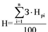
In wells built according to standard designs, only eccentricity and orientation are determined. The off-centerness of the wells is determined, as a rule, with the help of plumb lines or a rod (Fig. 5.). Well off-center is calculated by the formula
The off-center on the collectors is calculated by the formula
When shooting elements of underground utilities a prerequisite is a control measurement of the distances between them.

Figure: 5. Determination of the eccentricity of the well covers a- on the pipeline; b-on collector
2.3. VERTICAL SHOOTING
The altitude position of underground utilities, including the angles of their rotation, is determined prior to filling the trenches with technical leveling in accordance with the requirements of SN 212-73. The altitude position of the elements of the utility network in the straight-through collector is determined from the leveling course laid inside it.
If there is a dense network of benchmarks, the leveling is optional. In this case, the leveling of the elements of underground utilities for control is carried out by separate stations with reference to two benchmarks (Fig. 6).
 fig. 6.
  fig. 7.
Determination of elevations from the conditional beginning is prohibited.
When underground utilities are deeply laid, when the heights of the points of the communication elements cannot be obtained in the required places directly with a leveling or depth rail, these heights are obtained by measuring the vertical distance from the ring of the well to which the mark is transferred with a metal tape measure (Fig. 7).
Leveling determines the heights of the floor and top of the collector, the top and bottom of the cable duct in packages (blocks), the top of an armored cable, the top of pipelines, the surface of the earth (trench edges) in characteristic places, turning angles and points of change in the slopes of underground communications, shells of hatches and all the rest points captured in plan.
In the sewage system (fecal and stormwater), drainage and other gravity pipelines, pipe trays are leveled. In addition, the heights of the elements of all existing engineering communications, opened in trenches during construction, are determined.
For leveling, double-sided checker rods with a circular level are recommended. Differences in the elevations obtained on the black and red sides of the rails for each station should not exceed ± 5 mm. The distance from the tool to the rails should not be more than 100 m.
The heights of time benchmarks or points of the planned survey network are determined from the leveling line data with their inclusion in the line as tie points. Leveling them as intermediate points is not allowed.
The executive drawing is a document defining the type, structure, planned and high-rise location of the laid underground utilities.
The executive drawing is used as a source document when drawing up plans for underground utilities.
The executive drawing includes:
1) a topographic plan on a scale of 1: 500 or 1: 1000 depicting the relief by contours or heights, as well as existing and newly built underground communications;
2) longitudinal profile along the axis of the constructed structure;
3) plans and sections of wells (chambers);
4) cross-sections of collectors, channels, cases with an indication of the diameters of pipes located in them and brands of cables;
5) a catalog of coordinates of exits, turning angles and leading points on straight sections of underground utilities when surveying from points of a reference geodetic network and from points of a survey network.
Topographic base for drawing up the executive drawing of the constructed underground utilities, plans are used on a scale of 1: 500-1: 1000, obtained as a result of the executive topographic survey.
When accepting objects for operation, these plans are simultaneously a legal document confirming the correctness of transferring projects of underground communications, buildings, structures, roads, landscaping, landscaping and vertical planning of the territory to the area, as well as confirming the actual volume of construction.
Executive topographic survey is carried out in compliance with the requirements of SN 212-73 and within the boundaries of the construction site. The survey results are applied to the originals of plans stored in the geodetic fund of the city (village) or enterprise.
Longitudinal profile along the axis of the constructed underground structure is compiled according to the data of linear measurements and leveling of the structure elements carried out in nature.
The horizontal scale of the profile is taken to be equal to the scale of the plan, and the vertical scale is 1: 100 and, as an exception, in some cases, 1:10 (heating network).
On the longitudinal profile, in addition to the heights of the elements of underground utilities, the horizontal distances between the leveling points, the elevations of the bottom of the pipes and the magnitude of their slopes, the number of armored cables laid in the ground, the magnitude of the slopes, the type of wells, cases and clips, material and pipe diameters, design marks of the ground surface are shown and the characteristics of the surface coverage above the underground utilities, the structure of the underground structure and its foundation (material, brand, type) are given.
Plans and sections of wells (chambers), characteristic sections of collectors, channels, sweeps of cable wells and other details are drawn in a free space of the executive drawing in the scale adopted in the project, indicating the required linear dimensions that characterize the constructed structures.
With the same cross-section of blocks, canal tunnels, cases, one section is drawn up along the entire length.
When changing the section of the collector, channel, case. the number of pipes and cables in them, additional cross-sectional drawings are drawn up.
Coordinate catalog points of elements of underground utilities is compiled according to the established form in the adopted coordinate system.
2.5. REGISTRATION OF THE EXECUTIVE DRAWING
The first copy of the executive drawing, in addition to the catalog of coordinates, is made on tracing paper, drawn with ink in the accepted conventional signs, and, if necessary, supplemented with explanatory inscriptions.
The executive drawing for each underground engineering network must indicate: the name of the construction and installation organization, the type of underground structure, the name of the street (passage) of the settlement;
name of the design organization, number and date of project approval;
number and date of issue of the order of the administrative inspection for the right to carry out work on the excavation of areas for the laying of underground communications;
signatures of persons responsible for construction and installation works;
signatures of the persons who filmed and drawing up the executive drawing;
signatures of representatives of the customer and the operating organization.
In addition, as-built drawings must show all underground utilities crossing the underground network.
One executive drawing can be drawn up for the underground utilities combined in one trench (channel).
Not later than three days before backfilling of trenches, construction organizations are obliged to call the customer (developer) to carry out an instrumental check of the correctness of the planned and high-altitude position of the constructed underground utilities and to draw up executive drawings drawn up in accordance with the instructions of this Guide.
The inspectors enter the planned and height measurements in the outline and leveling log and certify with their signatures. On the executive drawing, the inspectors make the following inscription: "The executive drawing is checked, drawn up correctly and corresponds to nature." This inscription is accompanied by signatures and date.
As a result of the executive survey of the constructed underground utilities, the following materials should be obtained:
outlines for shooting underground utilities;
logs for measuring horizontal angles and leveling underground utilities;
schemes of theodolite and leveling moves;
statements of calculation of coordinates and heights;
the catalog of the coordinates of the points of the route for the undeveloped part;
executive drawing.
3. SURVEY OF EXISTING UNDERGROUND COMMUNICATIONS
3.1. GENERAL INFORMATION ABOUT THE ORGANIZATION AND CONTENT OF WORKS
Depending on the purpose of the plans, the survey of existing underground utilities can be performed in the optimal volume with the issuance of mandatory information or in the volume established by a special task.
In the optimal volume, surveying of existing underground communications is carried out to solve a number of design problems, during topographic surveying of the territories of cities and industrial enterprises subject to complete reconstruction, with state mapping on a large scale. On a special assignment, surveying of existing underground communications is carried out for inventory purposes, reconstruction of existing networks or their operation. The content of the work is given in table. 3. Survey of existing underground utilities is performed in combination with topographic survey of a site or as a special type of work performed using previously drawn up topographic plans. In either case, all field work on the site is entrusted either to one specialist, or they are differentiated by entrusting the performance of certain types of work to several specialists. In this case, most often, the actual filming work is separated from the specific work associated with finding and determining the technical characteristics of lifting communications.
The technological sequence of work on the survey of existing underground communications depends on the specifics of the object, the quality of previously drawn up topographic plans and the level of cartographic accounting in the field, as well as on the accepted option for organizing the work. Most often, especially in built-up areas, the following sequence of work is used:
build (or use a previously built) planned high-altitude survey network;
carry out a topographic survey of the site, including a survey of all structures of underground utilities, visible on the surface of the traces of excavations, entries into buildings and other elements of external signs of the presence of networks;
using the drawn up plans and data from the operating and other organizations, they draw up a preliminary layout of the networks; carry out reconnaissance of the area; carry out inspection and leveling of wells (chambers) of underground utilities in the required volume;
according to the survey, they clarify the network diagram and determine the places for working with cable detectors;
search and survey hidden points of underground communications;
according to the survey data, search and survey of hidden underground communications, they draw up a diagram of the reconstructed networks and agree with representatives of the organizations operating these networks.
When surveying underground utilities, there may be individual cases (especially in undeveloped areas) when the available topographic plans and data from operating organizations do not contain information sufficient to determine at least an approximate location of underground utilities. In these cases, in order to outline the direction of the filming justification, it is necessary to first perform reconnaissance and search for networks with their reliable fastening on the ground.
Table 3 |
||
| Survey of existing underground utilities | ||
| Types of work | in the optimal amount | in the amount established by a special assignment |
| Preparatory | Collection of information about the planned-high-altitude position and the purpose of underground utilities | Collection of information about the planned-high-altitude position, purpose and technical characteristics of underground utilities |
| Field |
planning and high-rise justification Filming of wells (cameras) and other structures of existing underground utilities Reconnaissance of underground communications Inspection of wells (chambers), inputs, digging sites Leveling underground utilities in optimal volume Finding hidden underground communications tions using tube detectors or digging Survey of the found points of underground communications Drawing up a diagram of the rectified underground utilities and coordination her with representatives of the exploiting organizations |
Build (use existing) planning and high-rise justification Coordination of wells (chambers) and other structures of existing underground utilities Reconnaissance of underground communications Detailed examination of wells (chambers), inputs, places of rupture Leveling all pipelines (cables) Finding hidden underground utilities with the help of cable detectors or by pitting Coordination of the found points to earth communications Drawing up a scheme of reconstructed underground communications and coordinating it with representatives of operating organizations |
| Cameral | Drawing up plans for underground communications tions combined with topographic plans our site |
Drawing up special plans for underground communications; catalogs of coordinates of underground utilities, technological schemes of certain types of networks; sketches of wells (chambers) |
3.2. OBJECTS AND SHOOTING TECHNIQUE
Surveying the structures of existing underground utilities located on the surface is, as a rule, an integral part of the topographic survey of the area.
The objects of shooting are the centers of manholes and chambers, exits to the surface of pipes and cables at entrances to buildings or in places of rupture, carpets, water columns, distribution cabinets, transformer booths and substations, pumping stations, heating points and other structures technologically related to existing underground communications.
Shooting is done in one of the following ways: coordination, polar, perpendicular and serifs, scale.
Coordination of the centers of manholes and corners of structures is carried out on a special assignment. It is performed from the points of theodolite moves of the first order, laid between the points of the reference geodetic networks, with the measurement of horizontal angles by two semi-receptions and lines in the forward and backward directions when measuring with measuring tape (tapes) or on two sides of the rangefinder rod when measuring with optical rangefinders. The maximum distances from the coordinated points to the points of theodolite moves should not exceed 50 m.Differences between the values \u200b\u200bof the angles (in minutes) obtained in half-receptions should not exceed the value
where L is the distance to the coordinated point, m.
In the overwhelming majority of cases, the same points are leveled simultaneously with coordination.
Polar survey is performed by theodolite from the points of the survey network. With the polar method, the angles are measured in one half-reception, and the lines are measured in one direction. Field measurements can be recorded directly in the horizontal survey outline.
The distances from the points of the theodolite to the underground utilities removed by the polar method should not exceed the values \u200b\u200bindicated in Table. 4.
The control of the correctness of the survey by the polar method is carried out by control measurements between the points taken. The length of control measurements should not exceed 50 m. If it is difficult to perform control linear measurements, the correctness of the survey by the polar method can be checked by measuring the angular directions from adjacent points with one semi-reception. In this case, the angle at the determined point should not be less than 30 ° and more than 150 °.
The method of perpendiculars and serifs consists in measuring the distances from the measuring tape (tape measure) laid in the target along the theodolite between the points of theodolite moves, as well as wells, supports and other points coordinated with the points of theodolite moves of the first order, as well as from the walls of buildings.
The lengths of the perpendiculars should not exceed:
4 m - when shooting at a scale of 1: 500
6 m - when shooting at a scale of 1: 1000
8 m - when shooting at a scale of 1: 2000
The serif lengths should not exceed the length of the measuring instrument.
Survey of underground utilities with a scale is allowed when shooting at a scale of 1: 1000 from the points of theodolite lines, and when shooting at a scale of 1: 2000 and 1: 5000, in addition, from points of scale or tacheometric lines.
Shooting of underground utility structures at a scale of 1: 500 with a scale is not recommended.
The maximum distances from the removed structures to the points of standing of the gauge should not exceed:
80 m - when shooting at a scale of 1: 1000
100 m - when shooting at a scale of 1: 2000
150 m - when shooting at a scale of 1: 5000
The results of field measurements are recorded in the mensulary log of the established form.
In the presence of aerial photography at a scale of 1: 5000 and larger, many wells (cameras), and sometimes the routes of underground utilities, can be deciphered in the images.
When interpreting underground utilities, it is recommended to use external signs: traces of trenches on the surface of the earth, changes in vegetation and soil cover, thawing of snow, etc. These signs are most clearly manifested in undeveloped areas.
When decrypting and shooting underground communications, it is necessary to take into account their purpose and device in order to correctly determine which type of communications wells (cameras) or opened pipes and cables belong to.
3.3. PREPARATORY WORK
Preparatory work, as a rule, is carried out after the completion of the survey of the area and the drawing up of a topographic plan to determine the methodology and the approximate volume of the forthcoming work on the survey and finding of underground communications. During the preparatory work, materials are collected on the existing underground utilities with the preparation of a network layout diagram.
The materials on the presence of underground utilities include:
executive drawings;
previously drawn up topographic plans (or their duplicates) with applied underground communications;
design master plans of the completed construction;
inventory data (number of wells, length of networks, pipe material and cable brand, gas pressure, etc.);
information from old-timers and representatives of operating organizations, confirmed by external signs of the presence of underground communications on the ground.
The layout of the networks in most cases is drawn up on a copy of the topographic plan of the work site. When drawing up a diagram, they strive for the greatest completeness of information about the underground utilities plotted on it. It is advisable, in particular, to indicate the sources that served as the basis for drawing communications on the diagram.
Upon completion of the preparatory work, using the drawn up network layout, you can determine the approximate amount of the following types of work:
compiling a description of underground communications;
leveling underground communications;
finding and shooting underground utilities using cable detectors.
The volume of description and leveling of underground utilities is equal to the number of wells (chambers) available at the work site. The volume of finding and surveying underground utilities using observation tubes is determined by the number of wellless turns, inputs and leading points on rectilinear communications. To determine the number of the latter, the total length of conductive communications should be calculated, then the resulting value should be divided by 20, 30, 50 or 100 m for shooting on a scale of 1: 500, respectively; 1: 1000.11: 8000.1: 5000.
The scope of work, determined during the preparatory work, is specified in the production of work on the survey of underground communications.
3.4. RECOGNOSCIATION, INSPECTION AND LEVELING OF UNDERGROUND
COMMUNICATIONS
Reconnaissance of underground communications is carried out in order to establish on the ground their types and locations, as well as to determine the sections of pipelines and cables to be found with the help of cable detectors.
The reconnaissance includes:
inspection of the work site;
locating wells, chambers, building entrances, openings and traces of buried trenches on the ground.
Inspection of the site should be carried out with a network layout diagram drawn up during the preparatory work, and preferably in the presence of a representative of the operating organization.
In the process of reconnaissance, each well is assigned a serial number. The numbering of wells in small survey areas, as a rule, is performed regardless of their purpose in ordinal numbers. In industrial enterprises, the numbering of wells is carried out according to the types of networks. To do this, knowing the approximate number of wells of each type of network, it is established that, for example, sewage wells will be numbered from 1 to 500, water pipes from 501 to 1000, etc. It is advisable to mark the numbers of the wells with paint on the hatch covers or walls of nearby buildings.
To search for buried wells, if necessary, devices based on the principle of a mine detector can be used.
An optimal survey of underground utilities aims to determine the following:
the purpose of underground communications; diameter and material of pipes, number of pipes and cables, places of their connections, inputs and outputs;
direction of flow of gravity communication.
The dimensions of wells and chambers for subsequent drawing on the plan are determined if their area and nature are not less than 4 m during shooting and at a scale of 1: 500 and 9 m -1: 1000. When shooting at scales of 1: 2000 and 1: 5000, the dimensions of wells and chambers are not determined.
The planned position of pipes, cables and channels in wells (chambers) often does not coincide with the projection of the center of the hatch, tied to the surface of the earth using the geodetic methods described above, therefore, when making surveys and scales of 1: 500 and 1: 1009, a planned binding of all incoming and outgoing gaskets is performed placed in a well or chamber. This requires:
design the center of the hatch on the plane, the location of the tied gaskets;
visually outline and design a reference line on the same plane from the projection of the center of the hatch in the direction of the attached pipeline or cable, using adjacent wells or external signs of the presence of underground utilities;
measure the shortest distances from the reference line to the points of intersection of the laying with the walls of the well, as well as to possible kinks of the pipeline inside the well.
The data obtained during the inspection of wells, including the results of tying pipes, cables and channels to the center of the hatch, are placed in the well survey log.
The survey materials of the wells allow you to start drawing up a reconnaissance scheme. Upon completion of the survey, all wells with their numbers, as well as buildings and structures associated with underground utilities, are applied to the diagram, the purpose and diameters of pipes (the number of cables) are indicated. The surveyed wells are connected to each other by lines when there is enough survey data for this. Usually, all gravity networks are fully identified during the survey of wells, and pressure pipelines and cable lines need to be privately located using cable detectors or by drilling. The scheme drawn up in this way serves to clarify the places of application of search devices. In the completed form, the scheme of the reconstructed networks is drawn up after the completion of work on the search for underground communications.
Leveling underground utilities includes determining the heights of the shells (top of the cast-iron ring of the manhole hatch), ground or paving at the well. as well as the heights of pipes, cables and channels located in the well.
When shooting at a scale of 1: 500 ^ 1: 5000, the height of the shells is determined from the results of technical (geometric) leveling on both sides of the rail. The permissible discrepancy between the elevations obtained on both sides of the rail should not exceed 20 mm.
The heights of the ground (paving) at the wells are determined on one side of the rail.
The results of leveling, if it is not performed during the coordination process, are recorded in the technical leveling log of the generally accepted form.
Determination of the heights of communications consists in measuring the excess between the shell and the communications using a metal tape measure or specially made measuring rods. In this case, the determination error should not exceed 10 mm.
In the wells of communications for various purposes, the following are subject to leveling:
in gravity sewers (gutters and drainage) - the bottom of the tray; in differential wells, in addition, the height of the bottom of the incoming pipes is determined;
on pipe gaskets - the top of the pipes; if there are pipe cuts at different levels, the heights of each adjacent pipe should be determined;
on heating systems laid in canals - the top and bottom of the canal. If there are channels of different dimensions in the well or adjacent at different levels, the heights of the top and bottom of each channel should be determined;
on cable networks - the place of intersection of the cable with the channel walls. If there is a bundle of cables located in a vertical plane, the heights of the upper and lower cables should be determined. If the bundle of cables is located in a channel, then determine the heights of the top and bottom of the channel.
The results of determining the heights of communications are recorded in the well survey log.
On a special assignment, in some cases, for the purposes of reconstruction and inventory, detailed surveys and leveling of underground utilities are carried out. At the same time, in addition to the above-mentioned scope of work, during the survey, in the optimal volume, the internal dimensions of the wells (chambers) are measured with reference to a relative to the line passing through the center of the hatch and to the directions to adjacent wells. Structural elements of pipelines and cables and their fittings are also subject to measurement. When leveling in these cases, the heights of all pipes, cables and channels entering and leaving the well (chamber) are determined relative to the shell.
The data of detailed measurements and leveling are recorded in the log of detailed inspection of wells.
CONCLUSION
1. LICENSING OF GEODETIC WORKS
For the right to carry out the above works, licenses are permissive. According to the legislation, licensing of geodetic works is authorized to be carried out by two federal departments: the Federal Service of Geodesy and Cartography and the State Construction Committee (Gosstroy RF).
The types of geodetic and cartographic activities and lists of works are established by the relevant provisions. They are specified and modified depending on the requirements of the national economy, but in general they correspond to the general nomenclature of geodetic and cartographic works.
To obtain licenses, the license applicant submits an application to the licensing authority - a request with the name of the activities and a list of works. In addition to the relevant documents of a legal nature (charter, certificate of state registration, certificates of registration with tax authorities, etc.), the applicant must justify with his qualifications and the availability of tools, and the licensing authority expert must confirm (check) the ability to perform the declared types activities and specific work.
When carrying out construction activities, they are licensed in the amount of SNiP 11-02-96 " Engineering survey»It is envisaged to obtain licenses if the surveyor intends to carry out the following types of work: creation (development) of geodetic reference networks; creation of high-altitude survey networks; updating topographic (engineering and topographic) plans; topographic surveys on a scale of 1: 10000 - 1: 200; ground phototopographic survey; aerial topographic surveys; stereophotogrammetric surveys; surveying underground structures; tracing of linear structures; engineering and hydrographic work; geodetic work related to the transfer to nature, with the binding of geotechnical workings, geodetic and other survey points; geodetic stationary observations of deformations of buildings, structures and the earth's surface in areas where hazardous natural and techno-natural processes develop; drawing up engineering and topographic plans.
If geodetic works are carried out during construction, then a license is required for: creating a geodetic base for construction; breakdown of on-site, except for main, linear structures or their parts, temporary buildings (structures); creation of an internal breakdown network of a building (structure); geodetic control of the accuracy of the geometric parameters of buildings (structures) and executive surveys with the preparation of executive geodetic documentation;
geodetic measurements of deformations of foundations, structures of buildings (structures) and their parts.
Verification of compliance with licensing requirements and conditions is carried out by persons authorized by the Gosstroy of Russia, the Federal Licensing Center under the Gosstroy of Russia, Roskartografiya or local territorial licensing authorities. If necessary, leading experts of expert base centers, research and educational organizations and institutions, testing laboratories licensed to carry out quality control participate in inspections as checking experts and consultants.
The heads of the audited organizations are required to provide auditors; free access to service and production premises, to technical documentation, to objects upon presentation of a notification, or a power of attorney for the right to check; provision of documents and information required for the inspection.
If the licensing conditions are not met, the license is suspended or canceled.
2. STANDARDIZATION IN ENGINEERING AND GEODETIC WORKS
Standardization is the process of establishing and applying rules in order to streamline human activities in a given area of \u200b\u200bproduction. The task of standardization in engineering and geodetic works is to ensure the uniformity of measurements, calculations and constructions in drawings and in nature. The solution to this problem is provided by a system of standards, norms and rules.
In Russia, there are four categories of standards that differ in their scope: the state all-Russian standard (GOST), the standard of the constituent entity of the Federation (SSF), the industry standard (OST) and the enterprise standard (STP). In the CIS countries, including our country, CMEA standards (not canceled) and ISO (introduced) are also in effect.
Directly related to geodetic works in construction are the standards of the "System for ensuring geometric accuracy in construction" group. These are GOST 21778 - 81 "Basic Provisions", GOST 21779 - 82 "Technological Tolerances", GOST 21780 - 83 "Precision Calculations", GOST 23616 - 79 "General Rules for Accuracy Control", GOST 26433.0 -85 "Measurement Rules". In the practice of geodetic work in construction, GOSTs are used from other sections related to geodetic terminology, geodetic instruments, measurement technology, etc.
3. SAFETY IN THE PERFORMANCE OF ENGINEERING AND GEODETIC WORKS
Engineering and geodetic work is carried out in various conditions: on the territories of cities and industrial facilities, in forest and hard-to-reach places, on sections of railways and highways, on buildings and structures under construction, on underground communications in our case, etc. To prevent accidents and injuries in these conditions, all work must be performed in compliance with special rules and safety instructions. In order to familiarize everyone, without exception, working with these rules, special briefings are held.
When performing geodetic works on construction sites, first of all, the general rules of construction safety are observed.
Wells, pits and other excavations in the ground, as well as openings in the ceilings of buildings and structures, are closed with shields or fenced off; in the dark, electric signal lamps are lit on these fences.
To descend to work places during the construction of structures with a depth of 25 m and more, passenger and cargo-passenger lifts (elevators) are used.
When performing work with the use of a laser beam, screens are installed in places where people can pass, excluding the spread of the beam outside the work area.
Students of vocational schools and technical schools under the age of 18, but not younger than 17 years of age, while undergoing practical training at construction sites in professions that provide for the performance of construction and installation work, which are subject to additional labor safety requirements, can work no more than three hours ... The work should be carried out under the guidance and supervision of a master of industrial training and an employee of a construction and installation organization appointed to guide the practice.
When performing geodetic works associated with construction, they comply with all safety rules established for this type of construction work, as well as specific ones.
Prior to the commencement of field topographic and geodetic works in urban conditions, settlements and on the territories of industrial facilities, schemes for the placement of hidden objects are established: underground communications and structures. When working in a city, you need to know the rules of the road; when working on roadways, it is necessary to wear unmasking (orange) clothing and put up protective shields. Work on streets and squares with heavy traffic is coordinated with the traffic police.
Survey of existing underground utilities, as a rule, is associated with their survey. During the examination, the covers of the wells are removed and a tripod with a "Danger" sign is placed near the wells.
Before people descend into the well, they check if there is gas in it by lowering a miner's lamp into it. If there is methane in the well, the lamp goes out or greatly reduces the intensity of the light, and in the presence of lighting gas, it flashes and goes out. From gasoline vapors, the lamp flame lengthens and turns blue, from ammonia gas it goes out without a flash. If the lamp does not go out, but burns with an even light (the same as on the surface), then there are no gases in the well and you can go down. Do not check the gas by smell, throwing lighted paper into the well, or lowering a burning candle or lantern.
During work, they monitor the open hatches, not allowing strangers to visit them. At the end of work or during a break, all hatches of the wells are tightly closed with lids. Tools, lamps and objects are lowered into the well on a rope after giving a conditional signal to the workers in the well. The well is illuminated with a miner's lamp. Work is carried out in mittens.
Metal slats are lowered into the well and removed from it in parts, without touching the wires.
Starting in 1993, the Gosstroy of Russia introduced standard instructions on labor protection for workers in the construction professions (TOI R66 -01; 02, etc.). More than 60 such instructions have been approved, the State Fire Service of the Ministry of Internal Affairs of the Russian Federation approved the Fire Safety Rules PPB, 3 parts over 10 issues. Guiding documents in construction (RDS) are also published.
The head of geodetic works at the construction site is obliged to study these standards, instruct subordinate workers and be responsible for their compliance.
BIBLIOGRAPHY
1. Grigorenko A.G., Kiselev M.I. Engineering geodesy.- M .: Higher school, 1983.
2. Klyushin EB, Mikhelev D. Sh., Kiselev MI, Feldman VD Engineering geodesy. - M .: Higher. shk., 2000.
3. Levchuk GP, Novak VE, Lebedev NN Applied geodesy. Geodetic work in the survey and construction of engineering structures.- Moscow: Nedra, 1983.
4. Workshop on applied geodesy. Geodetic support for the construction and operation of engineering structures.- Moscow: Nedra, 1993.
5. Guidelines for surveying and drawing up plans for underground communications and structures - M .: Stroyizdat, 1978.
6. Applied geodesy. Basic methods and principles of engineering and geodetic works. Edited by G.P. Levchuk - M .: Nedra, 1981.
Shallow and deep networks. Underground communications of the city are the most important element of engineering equipment and landscaping, meeting the necessary sanitary and hygienic requirements and providing a high level of amenities for the population. Underground communications include hot and cold water supply, gasification, power supply, alarm networks special purpose, telephony, radio broadcasting, telegraph, sewerage, drainage (storm sewerage), drainage, as well as new mastered types (pneumatic mail, garbage disposal), etc.
Urban underground communications are constantly evolving, representing a complex and important part of the urban "organism". Underground networks are subdivided into transit, trunk and distribution (distribution) networks.
The entire main network of trunk and transit pipelines, channels and cables is located under the city streets. Part of the networks is found under the carriageways of the streets. The laying of new and the reconstruction of existing networks, as well as emergency work on the networks, are accompanied by the destruction of streets, and when the networks are located under the carriageways, they cause violation of the road surface.
Urban underground networks are divided into pipelines, non-passable or semi-passable canals, passable underground gallery tunnels, called common collectors, and cable networks.
There are underground networks: transit, trunk and distribution (distribution). The last of them are located on the territories of microdistricts and quarters. Transit underground networks are characterized by the absence of branches on them. Trunk lines are usually laid under streets.
The transit ones include those underground communications that pass through the city, but are not used in the city, for example, a gas pipeline, an oil pipeline going from the field through this city.
The main networks of the city belong to the main networks, through which the main types of carriers in the city are supplied or taken off, designed for a large number of consumers. They are usually located in the direction of the main transport routes of the city.
Distribution (distribution) networks include those communications that branch off from the main ones and are brought directly to houses.
Underground networks have different depths. Shallow networks are located in the soil freezing zone. The depth of soil freezing is determined according to SNiP 23-01-99. For Moscow, for example, it is 140 cm.
Shallow networks include networks, the operation of which allows significant cooling: electric low-current and power cables, telephone and telegraph cables, signaling cables, gas pipelines, heating networks. Deep networks include underground utilities that cannot be overcooled: water supply, sewerage, drain. For underground networks, steel, concrete, reinforced concrete, asbestos-cement, ceramic and polyethylene pipelines can be used.
19. Arrangement of vertical planning in difficult terrain.
In conditions of significant differences in the heights of the relief of the territory of the microdistrict, urban planners use a large set of vertical planning techniques. With their help, they form the planning surface of the microdistrict territory, organize transport and pedestrian traffic between the terraces at different levels. In each specific case, one or another method or device of vertical planning is chosen depending on the properties of the soil, geological and hydrological conditions, and the requirements for the territory of the microdistrict.
The simplest element of the vertical planning of the territory when surfaces are mated with elevation differences is a slope. The main design issue is to establish its steepness. It is chosen from the conditions of soil stability, prevention of landslides and erosion. It depends on the height of the elevation difference. With a slope height of up to 6 m in stable soils (semi-rocky and similar), the steepness is expressed in a ratio from 1: 1 to 1: 0.5; with soils of medium stability - up to 1: 1.5; with loose soils (fine-grained sands and the like) - 1: 1.5 or less. To protect the slope from erosion by surface waters, trays, ditches, drain pipes buried in the ground are arranged at its bottom. Through them, rainwater is directed to the intake grates of the city drain or to the nearest reservoir. In addition, the slopes are strengthened by planting green spaces, sowed with grasses with a developed root system, covered with sod, paved with stones, concrete and reinforced concrete slabs. For the same purpose, cement-concrete slabs with holes filled with herbs or perennial flowers are used to place slopes. When using green spaces to anchor slopes, it is important to provide them with a vegetative layer of soil.
Slopes of great height (more than 5 m) are sometimes expedient to dissect in height by horizontal surfaces, which are called berms. Berms can be used for walking paths.
Instead of slopes, retaining walls are often arranged. They are made of durable material (stone, concrete, reinforced concrete) that can hold back the pressure of the overlying soil. Retaining walls are calculated in shape and section from the condition of equilibrium of earth masses, the height is determined by the height difference.
Retaining walls are made vertical and inclined (slopes 1:10 and 1:12). To prevent the soil of the overlying terrace from eroding, a drainage system and trays intercepting rain flows are provided in the upper terrace. Retaining walls are decorated with stone, rustication and other finishes.
For pedestrians, the terraces at different levels are connected by stairs. Ladders are arranged in slopes and breaks of retaining walls with a slope of no more than 1: 3, a riser height of 10 ... 14 cm. The width of the stair tread is not limited. When the slope is less than 1:13 (8%), it is allowed to arrange pedestrian inclined ramps. Stairs and ramps are arranged taking into account the main directions of the system of transport and pedestrian routes.
On the vertical planning project, design marks of characteristic points are indicated: at the corners and entrances of buildings, in places where the longitudinal slope changes and at the intersections of red lines of streets by passages, arrows in the street trays indicate directions and values \u200b\u200bof longitudinal slopes (in percent). In these directions, surface water runoff will occur. In addition to longitudinal slopes of driveways, sidewalks, green areas, as well as microdistrict sites, for the convenience of drainage of rainwater, transverse slopes are arranged.
The longitudinal and transverse slopes of all platforms and paths have such a direction that ensures the flow of water towards the nearest passage.
In the case of difficult terrain with slopes greater than the limiting ones adopted for sites, they are located in recesses, on embankments, or partially using a recess and embankment. At the same time, the architectural and planning combination of territories should not deteriorate.
The purpose of underground engineering and sanitary networks is to supply the city with water, electricity, heat, gas, etc., as well as to remove domestic and faecal and surface wastewater outside the city.
Services to the population and industrial enterprises are carried out by the following three main groups of underground engineering and sanitary networks:
- 1) pipelines;
- 2) cable networks;
- 3) tunnels (common collectors).
The first group includes: - urban sewage pipelines for domestic and fecal and industrial wastewater (with a separate city sewerage system); - drains for the removal of atmospheric waters (with a combined city sewage system, drains are combined with a network of domestic and fecal sewerage), - drainage pipes to lower the level of groundwater; - city water pipelines; - pipelines of the gas supply system (high, medium and low pressure); - district heating pipelines (heating systems); - special pipelines of industrial enterprises (oil pipelines, steam pipelines, kerosene pipelines, etc.).
The second group includes: - high and low voltage electric cables for outdoor street lighting, indoor lighting of buildings, for industrial purposes, as well as electric transport cables (trams, trolleybuses and subways); - low current electric cables - telephone, telegraph, radio broadcasting, intercity communications, fire and other types of alarm The third group includes: - underground galleries only for placing cables; - common collectors for joint placement, pipelines and cables.
Underground networks are subdivided into:
- a) transit for a city or a number of streets;
- b) breeders, serving houses and quarters of each street
- c) house (yard), laid within the territory of the quarter.
Transit underground networks are routed only along certain streets, taking into account their width and relief and in accordance with the future development of the city. These networks are placed under streets, squares, squares and boulevards and, in rare cases, in intra-block areas. Transit pipelines are of larger diameters than distribution pipelines.
Distribution underground networks are a necessary element of every street and square of the city.
The structures of underground urban networks must be calculated: - when located under the carriageway of the street - for the load of class H-13; - under impassable areas (sidewalks, squares, etc.) - for the load of class H-6. with the exception of gas, there are inspection wells for access to them; the number of such wells is approximately 40-50 pieces. 1 km of the street.
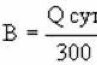
To lay each of the networks, it is required to dig a trench, the width of which depends on the diameter of the pipeline or cable. At present, experimental laying of pipelines and cables under the streets without breaking trenches is being carried out - by horizontal drilling and punching methods using productive mechanisms. The advantages of these progressive methods of laying networks are obvious. 3.2 Methods for placing underground networks
Distances from underground networks to buildings, structures, green spaces and to neighboring underground networks are regulated.
All trenches of underground networks are located outside the zone of pressure in the soil from buildings, which helps to preserve the integrity of the base of the building's foundations, to protect it from erosion. The minimum distance values \u200b\u200bare given in SNiP 2.07.01-89 *. The underground engineering networks were laid in three ways:
- 1) in a separate way, when each communication is laid in the ground separately, in compliance with the appropriate sanitary-technological and construction conditions for placement, regardless of the methods and timing of the arrangement of the remaining communication;
- 2) in a combined way, when communications for various purposes are laid simultaneously in one trench;
- 3) in a combined collector, when networks for various purposes are located in one collector.
Underground communications of the city are the most important element of engineering equipment and landscaping, meeting the necessary sanitary and hygienic requirements and providing a high level of amenities for the population. Underground communications include networks of hot and cold water supply, gasification, power supply, special-purpose signaling, telephony, radio broadcasting, telegraph, sewerage, drainage (storm sewer), drainage, etc. Distribution (distribution) networks include those communications, which branch off from the main lines and are brought directly to the houses.
Underground networks have different depths. Shallow networks are located in the soil freezing zone, and deep networks are located below the freezing zone. The depth of soil freezing is determined according to SNiP 23-01-99. Shallow networks include networks, the operation of which allows significant cooling: electric low-current and power cables, telephone and telegraph cables, signaling cables, gas pipelines, heating networks. Deep networks include underground utilities that cannot be overcooled: water supply, sewerage, drain. For underground networks, steel, concrete, reinforced concrete, asbestos-cement, ceramic and polyethylene pipelines can be used.
Water supply. One of the necessary conditions for urban improvement is water supply. The water supply system takes into account the number of consumers and the rate of water consumption. There are standards for all categories of consumers. The population needs water to meet physiological needs: cooking, maintaining hygiene, household activities. The rate of water consumption by one person per day fluctuates depending on the degree of improvement of the city.
For the population of large cities, provided with cold and hot water supply, the rate of water consumption per person. is about 400 l / day. This rate includes the consumption of water for the needs of public utilities (baths, hairdressing salons, laundries, catering establishments, etc.). Another consumer of water is industrial enterprises, in almost all of which the technological process is associated with the consumption of a large amount of water. The city also takes into account the consumption of water for fire extinguishing, watering green spaces and, depending on climatic conditions, for watering the urban area.
Depending on the amount of water supplied, a water supply system is selected. They can represent two or more parallel threads. Water comes to consumers from a water supply source (rivers, groundwater, sea) through treatment facilities, where it is filtered, discolored, disinfected with chlorine, ozone, hydrogen or ultraviolet rays, desalinated and settled.
Pipelines are made of steel, cast iron, reinforced concrete and plastic, from polyvinyl chloride and polyethylene.
When designing water supply networks, it is very important to provide for maintaining the required water temperature in the pipes. Therefore, it should not be excessively cooled and heated. Therefore, it is accepted that water supply networks are usually laid underground. But with a technological and feasibility study, other types of placement are also allowed.
To exclude hypothermia and freezing of water pipes, the depth of their laying, counting to the bottom, should be 0.5 m more than the calculated depth of penetration into the soil of zero temperature, i.e. the depth of freezing of the soil. To prevent water heating in the summer season, the depth of pipelines should be taken at least 0.5 m, counting to the top of the pipes. The depth of the production pipelines must be checked from the condition of preventing water heating only if it is unacceptable for technological reasons.
The diameter of the pipes is taken by calculation in accordance with the instructions of SNiP 2.04.02-84. The diameter of the water supply pipes, combined with the fire-prevention one, for urban areas is not less than 100 and not more than 1000 mm. The water supply network maintains a free head of at least 10 m of water column, which makes it possible to use the water supply network to extinguish fires. For this purpose, along the entire length of the water supply network, after 150 m, special devices are installed to connect fire hoses - hydrants. The norms stipulate that for external fire extinguishing, a water flow rate of 100 l / s is required. On water supply networks, water supply wells are arranged for proper operation and repair. They are made from precast concrete or local materials. When the groundwater level is above the bottom of the well, waterproofing of its bottom and walls is provided 0.5 m above the groundwater level.
Hot water supply is arranged in cities with a high level of amenities. Hot water is supplied to residential buildings by quarterly centralized hot water supply systems from separate central heating points (CHP), which, as a rule, are located in the center of the serviced area. The heat output of the central heating station is chosen taking into account the prospective construction.
The hot water supply network is calculated with a centralized water supply system for two operating modes: hot water withdrawal mode during the hours of maximum water consumption; water circulation mode during the hours of minimum draw-off.
Sewerage.
Sewerage is a necessary system for cleaning settlements from wastewater. Its task is to remove water contaminated as a result of human household activities and the work of industrial enterprises that use water in the technological process.
Sewerage can be combined and separate. The common sewerage system carries out the drainage of storm wastewater by one system of pipelines, which comes after rain from urban areas through storm inlet grilles, and household and fecal waters coming from residential buildings. With a separate sewerage system, two independent wastewater disposal systems are used: storm sewerage (drain), household and fecal. Waste water from industrial enterprises is discharged by a separate system to neutralize them from specific contaminants. Currently, a separate sewerage system is most applicable.
Sewerage not only removes wastewater from buildings, but also purifies them to such an extent that when they are discharged into a reservoir, they do not violate its sanitary conditions. For this purpose, sewer networks, pumping stations for pumping, facilities for wastewater treatment and for the release of treated wastewater are used.
Inspection wells are arranged in all places where the direction, diameter or slope change, at the points of connection of the side lines. In addition, inspection wells are built at certain distances on all pipelines to monitor their condition and timely cleaning. Currently, wells are unified and subdivided into small - for pipes with a diameter of up to 600 mm and large - over 600 mm. In terms of shape, typical wells are round, rectangular, trapezoidal. The most economical in terms of concrete consumption and the easiest to manufacture are round wells.
Heat supply. Thermal energy is required for the operation of industrial enterprises, heating, ventilation, air conditioning and centralized hot water supply of buildings. Housing and communal services use about 25% of all heat energy consumed by the city.
Trunk networks are located in the main directions from the heat source and consist of pipes of large diameters - from 400 to 1200 mm. Distribution networks have a diameter of branch pipelines from the main ones from 100 to 300 mm, and the diameter of pipelines leading to consumers - from 50 to 150 mm.
When choosing a method for laying heat pipes, the main task is to ensure the durability, reliability and economy of the solution.
The route of heating networks in cities is laid in technical strips allocated for engineering networks parallel to the red lines of streets, roads and driveways outside the carriageway and a strip of green spaces, but when justified, it is allowed to locate the heating mains under the carriageway or street sidewalk. Heating systems must not be laid along the edges of terraces, ravines or artificial excavations in case of subsiding soils.
The slope of heating networks, regardless of the direction of movement of the coolant and the method of laying, must be at least 0.002. Gas supply. Thanks to the development of the gas industry in our country, most villages and cities are gasified. Gas is used in industry and housing and communal services. It is transported through pipelines from fields over long distances and arrives at the consumer in the form of a combustible mixture of hydrocarbon, hydrogen and carbon monoxide. Gas consumption rates depend on the equipment of the apartment, climatic conditions, the level of development of public services. For example, the gas consumption rate in an apartment with a gas stove and hot water supply is taken as 77 m3 / year for 1 person, and in an apartment with a gas stove and gas water heater for hot water supply - 160 m3 / year.
The city gas supply system consists of gas pipelines, gas control points and service facilities.
Gas pipelines transporting wet gas are laid below the zone of seasonal soil freezing with slopes of 0.002 towards the condensate collectors. Gas pipelines transporting dried gas, when laid in non-heaving soils, may be located in the zone of seasonal soil freezing.
Power supply. The modern city is a complex complex of various consumers of electrical energy. The bulk of electricity is consumed by industry (about 70%). In recent years, the field of use of electricity for household needs, accounting for an average of 20% of total consumption, has significantly expanded. Depending on the size of the city, climatic conditions, the development of industry in it and many other factors, the share of the utilities load and specific power consumption (per 1 inhabitant or per 1 m2 of living space) can vary within wide limits.
The transmission of electricity to consumers within residential areas is carried out by underground cable lines, which are laid on the strip between the red line and the building line. Laying of underground power cable lines is usually carried out in common trenches. In cases of intersections with main routes and railways, with a lack of free space in the cross-section of the street and in some other cases, the laying of power cables is allowed in common collectors, and the power cables must be located in the collector above other engineering networks.
Maintenance of the microdistrict equipment. The housing stock is one of the most complex sectors of the municipal economy, requiring further improvement of operation and new forms of management using automation, telemechanics and computer technology.
In the conditions of urban development and during the reconstruction of existing enterprises, where underground communications are located in significant volumes (water supply, sewerage, drains, heating and cable networks), the laying of new and replacement of old underground networks by open means is difficult. An open way of laying communications under railway and tram tracks, city streets with heavy traffic is almost impossible. In this regard, in recent years, open and closed methods of laying communications have begun to be widely used. The closed method allows to reduce the volume of earthworks by 60-80% and to carry out construction in winter conditions without large increases in cost. With the closed method, it is possible to develop the soil and lay communications using shield penetration, punching, puncture and horizontal drilling. Underground facilities also include underground structures buried in the ground, such as pumping stations for water intake and pumping, underground storage facilities, warehouses and tunnels.
The complex process of setting up tunnels consists of laying out tunnel routes, strengthening foundations near buildings located, erecting a vertical shaft of the route for lowering and lifting tunneling shields, workers, lifting soil from the tunnel, supplying materials to the tunnel for ventilation, drainage
At the moment, in every city, region, world and state as a whole, communal infrastructure is very developed, which is designed to help meet the daily needs of citizens. at the moment, it is difficult to imagine the lack of running water, hot or cold water, basic sanitary facilities, or gas and heating. These or those communications are used by all of us on a daily basis. All kinds of engineering underground communications have been created to provide the population with the necessary utilities.
So what are underground utilities?
Underground utilities are, in most cases, linear structures, which function for the purpose of transporting water, gas and electricity. These structures are in the form of pipelines, cable or linear collectors.
Pipeline
A pipeline is an engineering structure, the main function of which is the transportation of all kinds of liquid substances under the influence of the pressure amplitude in the cross-sections of this device.
For its part, pipelines are classified into pressure and gravity. Products in liquid and gaseous state are transported by means of a pressure pipeline. The pressure pipeline acts as a water supply, district heating, pipeline and special-purpose gas pipeline. By means of a gravity pipeline, sewage, atmospheric and ground waters are removed in order to lower (drainage) their level.
Cable line
A cable line is a line for transporting electricity or its individual impulses and, in most cases, consists of one or more parallel cables connected to each other. Cable lines are classified as high or low voltage power cables and are used in telephony, telegraphy, television, radio broadcasting, etc.
Collector
The collector is a technical element used in boiler rooms, heating and water supply systems, for the purpose of mixing or dispensing substances from parallel branches. Collectors help with the purpose of the combined equipment of engineering communications for all kinds of purposes, in most cases, it is a water supply system, heating or power lines.
Having understood the circumstances of the need to install engineering underground communications, we will analyze the principles and the technological process by which all this is made possible.
Rules for the placement of underground utilities
Underground engineering communications are usually located at a distance of at least 2-3 meters from the foundations of nearby structures. The critical distance between communications for various purposes in height and plan should correspond to 0.5-1 meters.
The margin of error is from 10 to 15 centimeters. The accuracy of the high-rise placement of communications depends on the slopes and design elevations. The permissible error of marks for gravity pipelines can be no more than 5–10 mm, for pressure pipes - 30 mm, in other cases - 50 mm.
tie-ins and bends in gravity networks are equipped with wells. On the driveway, underground communications should be placed parallel to the red lines of nearby buildings. Water, heat and gas inlets to structures are installed at right angles to the building contour.
The diameters of gravity pipelines and the diameters of heating systems can increase in wells, in the direction from the serviced structures to the collector main. The diameter of the pressure pipe can also increase in the interwell span, this increase is similar to that for gravity communications. For underground utilities, the presence of breaks is unacceptable.
Types of engineering communications on the modern market
In order to raise the level of the communal infrastructure of our country as best and with the best quality as possible, many modern and high-tech devices and devices are presented on the domestic market, including:
- pVC pipes for outdoor sewerage;
- drainage pipes;
- drainage wells (http://www.standartpark-spb.ru/catalog/drenazhnye-kolodtsy-pl/drenazhnye-kolodtsy/);
- drainage tunnels;
- drainage blocks - systems for infiltration and accumulation EcoBloc.

What are the above engineering devices intended for?
PVC pipes for outdoor sewerage - used during installation, replacement or repair of damaged networks. The scope of application is the transportation of household, industrial and rainwater.
- Drain pipes (see here) are pipes used to drain excess fluid from a building.
- Drainage wells are part of the drainage system that serves as a method of combating groundwater in order to prevent yield decline and destruction of the foundation of the land.
- Drainage tunnels are a very effective method of draining wastewater from the ground, parking, roof of a building, lawn, etc.
Drainage blocks - EcoBloc infiltration and storage systems - help for all kinds of stormwater drainage combinations, used in the design of commercial and industrial areas, roads and highway construction.