GOST 577 68 dial indicators with a scale of 0 01 mm. Marking, packaging, transportation and storage
STATE STANDARD OF THE UNION OF SSR
CLOCK TYPE INDICATORS
WITH DIVISION PRICE 0.01 mm
TECHNICAL CONDITIONS
GOST 577-68
(ST SEV 3138-81)
USSR STATE MANAGEMENT COMMITTEE
PRODUCT QUALITY AND STANDARDS
Moscow
STATE STANDARD OF THE UNION OF SSR
Validityc
01.07.68
until 01.01.2000
This standard applies to dial indicators (hereinafter referred to as indicators) with a graduation of 0.01 mm and measuring ranges up to 25 mm.
The terms used in the standard and their definitions are given in the reference annex.
(Modified edition, Amendments No. 4, 5).
1. BASIC PARAMETERS AND DIMENSIONS
1.1. Indicators should be made with measurement ranges: 0-2, 0-5, 0-10, 0-25 mm.
1.2. Indicators with a measuring range of 0-2 mm should be made in two versions:
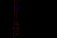
ICh - with the movement of the measuring rod parallel to the scale ();
IT - with the movement of the measuring rod perpendicular to the scale ().
Indicators with other measurement ranges should be manufactured in IC ().

1 - case; 2 - dial; 3 - rim; 4 - arrow; 5 - pointer; 6 - sleeve; 7 - measuring rod; 8 - measuring tip; 9- pointer of zero tolerance.

1 - case; 2 - dial; 3 - rim; 4 - arrow; 5 - pointer; 6 - sleeve; 7 - measuring rod; 8 - measuring tip.
Heck. 2
(Modified edition, Amendment No. 4).
1.3. (Deleted, Amendment No. 4).
1.4. According to the design of the case, the indicators are divided into ordinary, splash-proof and dust-proof.
The design that protects the indicator mechanism from dirt and mechanical damage is considered common.
Splash-proof is the design that protects the indicator mechanism from splashing while being in a spray-carrying environment.
Dustproof is the design that protects the indicator mechanism from dust when it is in air with an increased concentration of dust.
1.4.1. At the request of the consumer, indicators of splash- and dust-proof versions should be made with fastening by the eyelet.
1.4.2. At the request of the consumer, indicators with a shock-resistant mechanism (with a damping or other device) should be made with a sleeve or an eyelet.
1.4.1, 1.4.2. (Modified edition, Amendment No. 4).
1.5. Indicators must be supplied in two accuracy classes: 0 and 1.
Legend examples
indicator of IC performance with a measuring range of 0-2 mm, ordinary, accuracy class 0:
ICh02 indicator cl. 0 GOST 577-68
indicator of performance ICh with a measuring range of 0-10 mm, splash-proof, accuracy class 1:
Indicator ICh10B cl. 1 GOST 577-68
performance indicator IT, dustproof, accuracy class 1:
ITP indicator cl. 1 GOST 577-68
indicator of performance ICh with a measuring range of 0-10 mm, with a mechanism protected from shock, accuracy class 1:
ICh10R indicator cl. 1 GOST 577-68
indicator of performance ICh with a measuring range of 0-25 mm, ordinary, accuracy class 1:
Indicator I Ch25 cl. 1 GOST 577-68
1.4.1-1.5. (Modified edition, Amendment No. 4).
in terms of fastening - according to GOST 15593-70.
1.7. Largest indicator diameter D max should not exceed, mm:
42 - for indicators with a measuring range of 0-2 mm;
60 - for indicators with a measurement range of 0-5, 0-10 mm;
100 - for indicators with a measuring range of 0-25 mm.
1.6, 1.7. (Introduced additionally, Amendment No. 4).
2. TECHNICAL REQUIREMENTS
2.1. Indicators must be manufactured in accordance with the requirements of this standard for technical documentation approved in the prescribed manner.
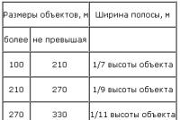
Table 1
|
table 2
|
6. The limitation of the period of validity has been removed according to the protocol N 7-95 of the Interstate Council for Standardization, Metrology and Certification (IUS 11-95)
7. EDITION (July 2002) with Amendments No. 2, 3, 4, 5, approved in May 1975, March 1979, June 1982, October 1984, July 1987 (IUS 7 -75, 5-79, 10-82, 1-85, 11-87)
This standard applies to dial indicators (hereinafter - indicators) with a graduation of 0.01 mm and measuring ranges up to 25 mm.
The terms used in the standard and their definitions are given in the appendix.
1. BASIC PARAMETERS AND DIMENSIONS
1.1. Indicators should be made with measurement ranges: 0-2, 0-5, 0-10, 0-25 mm.
1.2. Indicators with a measuring range of 0-2 mm should be made in two versions:
ICh - with the movement of the measuring rod parallel to the scale (Fig. 1);
IT - with the movement of the measuring rod perpendicular to the scale (Fig. 2).
Indicators with other measurement ranges should be made in IC versions (Fig. 1).
Heck. one
1 - body; 2 - clock face; 3 - bezel; 4 - arrow; 5 - pointer; 6 - sleeve; 7 - measuring rod; 8 - measuring tip; 9 - indicator of the tolerance field
Heck. 2
1 - body; 2 - clock face; 3 - bezel; 4 - arrow; 5 - pointer; 6 - sleeve; 7 - measuring rod; 8 - measuring tip
1.3. (Deleted, Amendment No. 4).
1.4. According to the housing design, the indicators are divided into ordinary, splash-proof and dust-proof.
The design that protects the indicator mechanism from dirt and mechanical damage is considered common.
Splash-proof is the design that protects the indicator mechanism from splashing while being in a spray-carrying environment.
Dustproof is the design that protects the indicator mechanism from dust when it is in air with an increased concentration of dust.
1.4.1. At the request of the consumer, indicators of splash- and dust-proof versions should be made with fastening by the eyelet.
1.4.2. At the request of the consumer, indicators with a shock-proof mechanism (with a damping or other device) should be made with an eyelet attachment.
1.5. Indicators must be supplied in two accuracy classes: 0 and 1.
Legend examples
indicator of IC performance with a measuring range of 0-2 mm, ordinary, accuracy class 0:
ICh02 indicator cl. 0GOST 577-68
indicator of performance ICh with a measuring range of 0-10 mm, splash-proof, accuracy class 1:
Indicator ICh10B cl. oneGOST 577-68
performance indicator IT, dustproof, accuracy class 1:
ITP indicator cl. oneGOST 577-68
indicator of performance ICh with a measuring range of 0-10 mm, with a mechanism protected from shock, accuracy class 1:
Indicator ICh 10R cl. oneGOST 577-68
indicator of performance ICh with a measuring range of 0-25 mm, ordinary, accuracy class 1:
ICh25 indicator cl. oneGOST 577-68
1.4.1-1.5. (Modified edition, Amendment N 4).
1.6. Connecting dimensions and versions of indicators in terms of fastening - in accordance with GOST 15593.
1.7. The largest diameter of the indicator should not exceed, mm:
42 - for indicators with a measuring range of 0-2 mm;
60 - for indicators with a measurement range of 0-5, 0-10 mm;
100 - for indicators with a measuring range of 0-25 mm.
1.6, 1.7. (Introduced additionally, Amendment N 4).
2. TECHNICAL REQUIREMENTS
2.1. Indicators must be manufactured in accordance with the requirements of this standard for technical documentation approved in the prescribed manner.
2.2. Metrological characteristics of indicators should not exceed the values \u200b\u200bindicated in Table 1.
Table 1
Accuracy class | Greatest difference of indicator errors, microns | The range of indications of the indicator for the measurement range, μm | Variation of indicator readings for the measurement range, μm |
||||||||
in any part of the measurement range, mm | in the entire measuring range, mm | ||||||||||
up to 10 mm | before. 10 mm * | st. 10 mm * | st. 10 mm |
||||||||
_________________
* Probably a mistake in the original. Read "over 10 mm" and "up to 10 mm" respectively. - Note from the manufacturer of the database.
Notes:
1. By 0.1, 1 we mean the algebraic differences of the ordinates of the highest and the lowest points of the indicator error curve within any section with a length of 0.1 mm, respectively (0.1 - Fig. 4) and 1 mm (1 - Fig. 3) measuring range for forward or reverse stroke of the measuring rod.
2. Under 2, 3, 5, 10 and 25 understand the algebraic differences of the ordinates of the highest and lowest points of the error curve of the indicator with the measurement range, respectively, 0-2 mm (2), 0-3 mm (3), 0-5 mm ( 5), 0-10 mm (10) and 0-25 mm (25) with forward or reverse stroke of the measuring rod.
2.3. Measuring force and its fluctuation should not exceed the values \u200b\u200bindicated in table 2.
table 2
Measurement range, mm | The greatest measuring force with a forward stroke, | Fluctuation of the measuring force, at | ||||
forward or reverse | changing the direction of movement of the measuring rod | |||||
Note. Increased values \u200b\u200bof the maximum measuring force and its fluctuations are allowed for indicators of splash-, dust-proof design and with a mechanism that is protected from shock.
2.2, 2.3. (Modified edition, Amendment N 4).
2.4. Deviation from cylindrical sleeve 6
(Fig. 1, 2) should not exceed 8 microns.
2.5. The total stroke of the measuring rod should exceed the working one, mm, not less than by:
0.3 - for indicators with a measuring range of 0-2 mm;
0.5 - for indicators with a measurement range of 0-5 and 0-10 mm;
1.0 - for indicators with a measuring range of 0-25 mm.
Heck. 3
Indicator error curves
Heck. 4
2.6. The change in the indicator reading when pressing on the measuring rod in the direction perpendicular to its axis with a force of 2-2.5 N should not exceed 0.5 scale divisions for indicators with a measuring range of up to 10 mm and 1.5 scale divisions for indicators with a range measurements over 10 mm.
2.7. The arrow and scale elements (dashes, numbers) must be clearly visible against the background of the dial.
2.8. The division length must be at least 1 mm.
2.9. The stroke width should be 0.15-0.25 mm.
The difference in the width of individual lines within one scale should not exceed 0.05 mm. It is allowed to make indicators with strokes 0.25-0.35 mm wide for measuring ranges over 10 mm.
2.10. Every fifth division of the scale should be marked with an elongated stroke. Every tenth division should be marked with the corresponding division number. Digitization of the scale should be double and different in color (black and red). The numeric marks on the scale should be applied in two directions for indicators with upper measurement limits up to 10 mm and in one direction - for indicators with upper measurement limits over 10 mm.
2.5.-2.10. (Modified edition, Amendment N 4).
2.11. (Deleted, Amendment No. 4).
2.12. The width of the arrow in that part of it, which is above the scale, should be within 0.15-0.20 mm. The end of the arrow should overlap the short scale lines by at least 0.3 and not more than 0.8 of their length. The distance between the end of the hand and the dial must not exceed 0.7 mm.
2.13. The pointer must be mounted on the axle in such a way that it does not rotate when the measuring rod moves freely or when it stops abruptly.
2.14. In both extreme positions of the double stroke of the measuring rod, the arrow should cross the axis of symmetry by at least 5 divisions for indicators with an upper measurement limit of up to 3 mm and by 10 divisions for indicators with an upper measurement limit of more than 3 mm.
2.12-2.14. (Modified edition, Amendment N 4).
2.14.1. The dial should be covered with a transparent material that does not have defects that interfere with the reading.
(Introduced additionally, Amendment N 4).
2.15. Indicators should be made with a speed indicator and movable indicators of the tolerance field. It is allowed, upon the customer's request, to manufacture indicators without movable indicators of the tolerance field.
The digitization of the pointer scale should be black and correspond to the forward travel scale.
2.16. When the indicator is set to the indicator of revolutions at any number of full revolutions, the deviation of the arrow from the direction of the axis of the measuring rod of the indicator should not exceed 15 divisions, for indicators with an upper measurement limit of up to 10 mm and 20 divisions - for indicators with an upper measurement limit of more than 10 mm.
2.17. Indicators must have a device for aligning the arrow with any scale division. The device must work smoothly, without jamming and protect against spontaneous movement of the arrow from the set position.
2.18. The connecting sleeve and the measuring rod of the indicator should be made of tool steel or stainless steel.
2.19. The outer metal surfaces of the indicators, with the exception of the measuring one, must have a reliable protective coating.
2.20. The roughness parameter according to GOST 2789 of the outer surface of the connecting sleeve should be no more than 0.63 microns. The roughness parameter of the working surface of the measuring tip should be no more than 0.1 µm.
2.15-2.20. (Modified edition, Amendment N 4).
2.21. Mean time between failures not less than:
500,000 conventional measurements for indicators with a measurement range of 0-2 mm (IT versions);
1,000,000 conventional measurements for indicators with a measurement range of 0-2 mm (IC versions), 0-5 and 0-10 mm;
500,000 conventional measurements for indicators with a measuring range of 0-25 mm.
Installed trouble-free operating time, respectively, not less:
75,000, 150,000, 50,000 conventional measurements.
The failure criterion is the failure of indicators to meet the requirements of clause 2.2.
2.21.1. The hardness of the measuring surface of the steel tips must be at least 61 HRC.
2.21, 2.21.1. (Modified edition, Amendment N 6).
2.22. The operating time to the first failure with a probability of 0.85 must be at least:
500,000 conditional measurements | for indicators with an upper measurement limit of up to 10 mm; |
|
150000 " " | for indicators with an upper measurement limit over 10 mm; |
|
1,000,000 conventional measurements | for indicators with an upper measurement limit of up to 10 mm, which have been awarded the State Quality Mark in accordance with the established procedure. |
(Modified edition, Amendment N 4).
2.23. Full average service life - at least 6 years.
The established full service life is at least 2 years.
The criterion for the limiting state is the limiting wear of the teeth of the rack and pinion and rack, characterized by the impossibility of their restoration by mechanical processing.
2.24 (Deleted, Amendment No. 4).
2a. COMPLETENESS
2a.1. At the request of the consumer, the indicator kit should include:
rim stopper;
a device for removing the measuring rod;
an elongated tip made of hard alloy NRDS-1.6 or NRDS-5 2nd class of accuracy according to GOST 11007;
steel extended measuring tip NRDS-0.6 2nd accuracy class according to GOST 11007
2b. RULES OF ACCEPTANCE
2b.1. To check the compliance of indicators with the requirements of this standard, state tests, acceptance control and periodic tests and tests for reliability are carried out.
2b.2. State tests - according to GOST 8.383 * and GOST 8.001 *.
________________
* PR 50.2.009-94 are valid on the territory of the Russian Federation.
The document is not valid on the territory of the Russian Federation. The Procedure for testing standard samples or measuring instruments for the purpose of type approval, Administrative regulations on the provision by the Federal Agency for Technical Regulation and Metrology of the state service for the approval of the type of reference materials or the type of measuring instruments, Requirements for marks of approval of the type of reference materials or the type of measuring instruments and the procedure their application. - Note from the manufacturer of the database.
2b.3. During acceptance control, each indicator is checked for compliance with the requirements of clauses 2.2-2.8, 2.12 (in terms of overlapping lines and the distance between the end of the arrow and the dial), 2.13-2.15, 2.21.1.
2b.2, 2b.3. (Modified edition, Amendment N 5).
2b.4. Periodic tests are carried out at least once every three years on at least three indicators from among those that have passed acceptance control for compliance with all the requirements of this standard.
At the same time, the indicators of clause 2.23 are confirmed by the results of the analysis of controlled operation of at least five indicators according to RD 50-690.
If, during periodic tests, it is found that the indicators meet all the requirements of this standard, the results of the periodic tests are considered satisfactory.
(Modified edition, Amendments N 5, 6).
2b.5. Reliability tests are carried out every three years for compliance with the requirements of GOST 27.301.
(Introduced additionally, Amendment No. 6).
2c. CONTROL AND TEST METHODS
2 in 1. Checking indicators - according to MI 2192.
consumer risk \u003d 0.2;
the number of test items is at least five.
The control of the established trouble-free operating time is carried out at (according to clause 2.22) and the number of failures.
2c. 3. When checking the influence of transport shaking, a shock stand is used, which creates a shaking with an acceleration of 30 m / s and a frequency of 80-120 beats per minute. Boxes with packed indicators are fixed to the stand and tested with a total number of impacts of 15,000. After testing, the metrological characteristics of indicators should not exceed the values \u200b\u200bspecified in Table 1.
2c.4. The impact of climatic factors of the external environment during transportation is checked in climatic chambers. Tests are carried out in the following mode: first at a temperature of plus (50 ± 3) ° С, then minus (50 ± 3) ° С and then at a relative humidity of (95 ± 3)% at a temperature of 35 ° С. Exposure in climatic chambers in each mode for 2 hours. After the tests, the metrological characteristics of the indicators should not exceed the values \u200b\u200bindicated in Table 1.
Section 2c. (Introduced additionally, Amendment No. 6).
3. LABELING, PACKAGING, TRANSPORTATION AND STORAGE
3.1. Each indicator must be marked in accordance with GOST 13762, as well as:
value of division;
the serial number of the indicator according to the manufacturer's numbering system (on the case).
3.2. The case must contain:
name and performance of the indicator;
measurement range;
designation of this standard.
3.1, 3.2. (Modified edition, Amendment N 4).
3.3. The image of the State Quality Mark must be inscribed in the passport of indicators that have been appropriated with the State Quality Mark in accordance with the established procedure.
(Modified edition, Amendments N 4, 6).
3.4. Packing, transportation and storage of indicators - according to GOST 13762.
(Modified edition, Amendment N 4).
4. MANUFACTURER'S WARRANTIES
4.1. The manufacturer must ensure that the indicators comply with the requirements of this standard, subject to the conditions of operation, transportation and storage.
The warranty period of operation is 18 months from the date of putting the indicators into operation.
(Modified edition, Amendments N 4, 6).
APPENDIX (reference). TERMS USED IN THE STANDARD AND THEIR DEFINITIONS
APPENDIX
Reference
The range of readings is understood as the difference between the largest and the smallest readings of the indicator when the tip is locked five times on a fixed measuring surface.
Variation in readings is understood as the difference between the indicator readings at one point of the measurement range during the forward stroke and at the same point - during the reverse (the value of the displacement during the reverse stroke should not exceed 0.05 mm).
For the fluctuation of the measuring force when the direction of movement of the measuring rod is changed, the difference in the forces at the point to be checked in the middle of the measurement range is taken and when passing beyond it by 1-2 mm and returning to the checked point.
(Introduced additionally, Amendment N 4).
Electronic text of the document
prepared by Kodeks JSC and verified by:
official publication
Moscow: IPK Standards Publishing House, 2002
DISCLAIMER OF WARRANTY ON USE
The text is presented for information purposes only and may not be relevant
The print edition is fully updated for the current date
GOST 577-68
INTERSTATE STANDARD
CLOCK TYPE INDICATORS
WITH DIVISION PRICE 0.01 mm
TECHNICAL CONDITIONS
IPK PUBLISHING STANDARDS
Moscow
INTERSTATE STANDARD
Date of introduction 01.07.68
This standard applies to dial indicators (hereinafter - indicators) with a graduation of 0.01 mm and measuring ranges up to 25 mm.
Terms used in the standard and their definitions are given in.
(Modified edition, Amendments No. 4, 6).
1. BASIC PARAMETERS AND DIMENSIONS
1.1. Indicators should be made with measurement ranges: 0-2, 0-5, 0-10, 0-25 mm.
1.2. Indicators with a measuring range of 0-2 mm should be made in two versions:
ICh - with the movement of the measuring rod parallel to the scale (Fig.);
IT - with the movement of the measuring rod perpendicular to the scale (Fig.).
Indicators with other measuring ranges should be manufactured in IC versions (Fig.).
1.3. (Deleted, Amendment No. 4).
1.4. According to the case design, the indicators are divided into ordinary, splash-proof and dust-proof.
The design that protects the indicator mechanism from dirt and mechanical damage is considered common.
Splash-proof is the design that protects the indicator mechanism from splashing while being in a spray-carrying environment.
Dustproof is the design that protects the indicator mechanism from dust when it is in air with an increased concentration of dust.
1.4.1. At the request of the consumer, indicators of splash- and dust-proof versions should be made with fastening by the eyelet.
1.4.2. At the request of the consumer, indicators with a shock-resistant mechanism (with a damping or other device) should be made with a sleeve or an eyelet.
1.5. Indicators must be supplied in two accuracy classes: 0 and 1.
Legend examples
indicator of IC performance with a measuring range of 0-2 mm, ordinary, accuracy class 0:
ICh02 indicator cl. 0 GOST 577-68
indicator of performance ICh with a measuring range of 0-10 mm, splash-proof, accuracy class 1:
Indicator ICh10B cl. 1 GOST 577-68
performance indicator IT, dustproof, accuracy class 1:
ITP indicator cl. 1 GOST 577-68
indicator of performance ICh with a measuring range of 0-10 mm, with a mechanism protected from shock, accuracy class 1:
ICh10R indicator cl. 1 GOST 577-68
indicator of performance ICh with a measuring range of 0-25 mm, ordinary, accuracy class 1:
Indicator I Ch25 cl. 1 GOST 577-68
1.4.1 - 1.5. (Modified edition, Amendment No. 4).
in terms of fastening - according to GOST 15593.
1.7. Largest indicator diameter D max should not exceed, mm:
42 - for indicators with a measuring range of 0-2 mm;
60 - for indicators with a measurement range of 0-5, 0-10 mm;
100 - for indicators with a measuring range of 0-25 mm.
1.6, 1.7. (Introduced additionally, Amendment No. 4).
2. TECHNICAL REQUIREMENTS
2.1. Indicators must be manufactured in accordance with the requirements of this standard for technical documentation approved in the prescribed manner.
Table 1
| Greatest difference of indicator errors, microns | The range of indications of the indicator for the measuring range, μm | Variation of indicator readings for the measuring range, μm |
|||||||||
| in any part of the measuring range, mm | in the entire measuring range, mm |
||||||||||
| D 0.1 | D 10 | D 25 | up to 10 mm | up to 10 mm | st. 10 mm | st. 10 mm |
|||||
Notes I:
1. Under D 0.1, D 1 understand the algebraic differences of the ordinates of the highest and lowest points of the indicator error curve within any section with a length of 0.1 mm, respectively (D 0.1 - damn. ) and 1 mm (D 1 - damn. ) measuring range for forward or reverse stroke of the measuring rod.
2.Under D 2, D 3, D 5, D 10 and D 25 understand the algebraic differences of the ordinates of the highest and lowest points of the error curve of the indicator with a measurement range of 0-2 mm, respectively (D 2), 0-3 mm (D 3), 0-5 mm (D 5), 0-10 mm (D 10) and 0-25 mm (D 25) with forward or reverse stroke of the measuring rod.
2.3 The measuring force and its fluctuation should not exceed the values \u200b\u200bindicated in tab. ...
table 2
| The greatest measuring force with a forward stroke,H | Fluctuation of the measuring force,H, at |
||
| forward or reverse | changing the direction of movement of the measuring rod |
||
| 0-10 |
|||
| 0-25 | |||
Notes e. Increased values \u200b\u200bof the maximum measuring force and its fluctuations are allowed for indicators of splash-, dust-proof design and with a mechanism that is protected from shock.
2.2, 2.3. (Modified edition, Amendment No. 4).
2.4. Deviation from cylindrical sleeve 6 (drawing -) should not exceed 8 microns.
2.5 The total stroke of the measuring rod must exceed the working stroke, mm, not less than by:
0.3 - for indicators with a measuring range of 0-2 mm;
0.5 - for indicators with a measurement range of 0-5 and 0-10 mm;
1.0 - for indicators with a measuring range of 0-25 mm.
2.6. The change in the indicator reading when pressing the measuring rod in a direction perpendicular to its axis with a force of 2-2.5 N should not exceed 0.5 scale divisions for indicators with a measuring range of up to 10 mm and 1.5 scale divisions for indicators with a range measurements over 10 mm.
2.7. The arrow and scale elements (dashes, numbers) must be clearly visible against the background of the dial.
500,000 conventional measurements - for indicators with an upper limit of measurement up to 10 mm;
(from 01.01.1986 -200000
conditional measurements) - for indicators with an upper limit of measurement over 10 mm;
1,000,000 conventional measurements - for indicators with an upper limit of measurement up to 10 mm, which have been awarded the State Quality Mark in accordance with the established procedure.
2.23. Full average service life - at least 6 years. The established full service life is at least 2 years. The criterion of the limiting state is the limiting wear of the teeth of the rack and pinion and rack, characterized by the impossibility of their restoration by mechanical processing.
2.24. (Excluded, Amendment No. 4).
2a. COMPLETENESS
rim stopper;
a device for removing the measuring rod;
elongated tip made of hard alloy NRDS-1.6 or NRDS-5 2nd class of accuracy according to GOST 11007;
steel extended measuring tip NRDS-0.6 of the 2nd accuracy class in accordance with GOST 11007;
tip made of hard alloy with a flat measuring surface NRP-1 and NRP-8 2nd class of accuracy according to GOST 11007.
2b.2, 2b.3 (Modified edition, Amendment No. 5).
manufacturer's risk a \u003d 0.1;
consumer risk b \u003d 0.2;
the number of test items is at least five.
Control of the established failure-free operating time is carried out at T b \u003d T y (by) and the number of refusals FROM= 0.
2c. 3. When checking the influence of transport shaking, a shock stand is used, which creates shaking with an acceleration of 30 m / s 2 and a frequency of 80 - 120 beats per minute. Boxes with packed indicators are attached to the stand and tested with a total number of impacts of 15,000. After testing, the metrological characteristics of the indicators should not exceed the values \u200b\u200bindicated in table. ...
2c.4. The impact of climatic factors of the external environment during transportation is checked in climatic chambers. Tests are carried out in the following mode: first at a temperature of plus (50 ± 3) ° С, then minus (50 ± 3) ° С and then at a relative humidity of (95 ± 3)% at a temperature of 35 ° С. Exposure in climatic chambers in each mode for 2 hours. After the tests, the metrological characteristics of the indicators should not exceed the values \u200b\u200bindicated in table. ...
Sec. 2c. (Introduced additionally, Amendment No. 6).
3. LABELING, PACKAGING, TRANSPORTATION AND STORAGE
The range of readings is understood as the difference between the largest and the smallest readings of the indicator when the tip is locked five times on a fixed measuring surface.
Variation in readings is understood as the difference between the indicator readings at one point of the measurement range during the forward stroke and at the same point - during the reverse (the value of the displacement during the reverse stroke should not exceed 0.05 mm).
For the fluctuation of the measuring force when the direction of movement of the measuring rod is changed, the difference in the efforts at the point to be checked in the middle of the measurement range is taken and when going beyond it by 1 - 2 mm and returning to the point being checked.
STATE STANDARD
UNION SSR
TECHNICAL CONDITIONS
GOST 5 / 7-68 (ST SEV 3138-81)
Official edition
USSR STATE COMMITTEE ON PRODUCT QUALITY AND STANDARDS MANAGEMENT Moscow
UDC 681.2: 531.7: 006.354 Group P53
STATE STANDARD OF THE UNION OF SSR
CLOCK-TYPE INDICATORS WITH DIVISION PRICE 0.01 mm
Specifications
Clock-type dial indicators graduated in unit divisions of 0.01 mm. Specifications
(CT SEV 3138-81)
Valid from 01.07.6B
Failure to comply with the standard is punishable by law
This standard applies to dial indicators (hereinafter - indicators) with a graduation of 0.01 mm and measuring ranges up to 25 mm.
The terms used in the standard and their definitions are given in the reference annex.
(Modified edition, Amendments No. 4, 5).
1. BASIC PARAMETERS AND DIMENSIONS
1.1. Indicators should be made with measurement ranges: 0-2, 0-5, 0-10, 0-25 mm.
1.2. Indicators with a measuring range of 0-2 mm should be made in two versions:
ICh - with the movement of the measuring rod parallel to the scale (Fig. 1);
IT - with the movement of the measuring rod perpendicular to the scale (Fig. 2).
Official edition Reprinting prohibited
Indicators with other measuring ranges should be made in the version of IC (Fig. 1).

1-case, 2-dial; 3-bezel; 4-arrow, 5-pointer, 6-sleeve, 7-measuring rod, 6-measuring tip, 9-indicator of the tolerance zone

1.3. (Deleted, Amendment No. 4).
1.4. According to the housing design, the indicators are divided into ordinary, splash-proof and dust-proof.
The design that protects the indicator mechanism from dirt and mechanical damage is considered common.
Splash-proof is the design that protects the indicator mechanism from splashing while being in a spray-carrying environment.
Dustproof is the design that protects the indicator mechanism from the ingress of dust when it is in the air with an increased concentration of dust.
1.4.1. At the request of the consumer, indicators of splash- and dust-proof versions should be made with fastening by the eyelet.
1.4.2. At the request of the consumer, indicators with a shock-resistant mechanism (with a damping or other device) should be made with a sleeve or an eyelet.
1.4.1, 1.4.2. (Modified edition, Amendment No. 4).
1 5. Indicators must be supplied in two accuracy classes: O and 1.
Legend examples
indicator of IC performance with a measuring range of 0-2 mm, ordinary, accuracy class 0:
ICh02 indicator cl. 0 GOST 577-68
indicator of performance ICh with a measurement range of 0-10 mm, splash-proof, accuracy class 1;
Indicator I 410B cl. 1 GOST 577-68
performance indicator IT, dustproof, accuracy class 1:
ITP indicator cl. 1 GOST 577-68
indicator of performance ICh with a measuring range of 0-10 mm, with a mechanism protected from shock, accuracy class 1:
ICh10R indicator cl. 1 GOST 577-68
indicator of performance ICh with a measuring range of 0-25 mm, ordinary, accuracy class 1:
Indicator ICh25 cl. 1 GOST 577-68
1.4.1-1.5. (Modified edition, Amendment No. 4).
1.6. Connecting dimensions and versions of indicators in terms of fastening - according to GOST 15593-70.
1.7. The largest diameter of the indicator D maK should not exceed, mm:
42 - for indicators with a measuring range of 0-2 mm;
60 - for indicators with a measurement range of 0-5, 0-10 mm;
100 - for indicators with a measuring range of 0-25 mm.
1.6, 1.7. (Introduced additionally, Amendment No. 4).
2. TECHNICAL REQUIREMENTS
2.1. Indicators must be manufactured in accordance with the requirements of this standard for technical documentation approved in the prescribed manner.
2.2. Metrological characteristics of indicators should not exceed the values \u200b\u200bindicated in table. one.
The range of indications of the indicator for the measuring range, μm
up to 10 mm I up to 10 mm
Table I
Variation of indicator readings for the measuring range, μm
Notes:
1. DE, 1, D1 mean the algebraic differences between the ordinates of the highest and lowest points of the indicator error curve within any section of length 0.1 mm, respectively (DO, 1-fig. 4) and 1 mm (A 1-fig. 3 ) measuring range for forward or backward stroke of the measuring rod.
2. Under D2, DZ, D5, D10 and D25 understand the algebraic differences of the ordinates of the highest and lowest points of the error curve of the indicator with the measurement range, respectively, O-2 mm (D2), S -3 mm (DZ), 0-5 mm (D 5) "0-10 mm (D 10) and 0-2 5 mm (D25) with forward or reverse stroke of the measuring rod.
2.3 The measuring force and its fluctuation should not exceed the values \u200b\u200bindicated in table. 2.
table 2
Note Increased values \u200b\u200bof the maximum measuring force and its fluctuations are allowed for indicators of splash-proof, dust-proof design and with a mechanism that is protected from shock.
2.4. The deviation from the cylindrical sleeve 6 (Fig. 1-3) should not exceed 8 microns.
2.5 The total stroke of the measuring rod must exceed the working stroke, mm, not less than by:
0.3 - for indicators with a measuring range of 0-2 mm;
0.5 - for indicators with a measurement range of 0-5 and 0-10 mm;
1.0 - for indicators with a measuring range of 0-25 mm.
Indicator error curves


(Modified edition, Amendment No. 4).
2.6. The change in the indicator reading when pressing the measuring rod in a direction perpendicular to its axis with a force of 2-2.5 N should not exceed 0.5 divisions of the scale for
indicators with a measuring range up to 10 mm and 1.5 scale divisions - for indicators with a measuring range over 10 mm.
2.7. The arrow and scale elements (dashes, numbers) must be clearly visible against the background of the dial.
2.8. The division length must be at least 1 mm.
2.9. The stroke width should be 0.15-0.25 mm.
The difference in the width of individual lines within one scale should not exceed 0.05 mm. It is allowed to make indicators with strokes 0.25-0.35 mm wide for measuring ranges over 10 mm.
2.10. Every fifth division of the scale should be marked with an elongated stroke. Every tenth division should be marked with the corresponding division number. Digitization of the scale should be double and different in color (black and red). The numeric marks on the scale should be applied in two directions for indicators with upper measurement limits up to 10 mm and in one direction - for indicators with upper measurement limits over 10 mm.
2.5-2.10. (Modified edition, Amendment No. 4).
2.11. (Deleted, Amendment No. 4).
2.12. The width of the arrow in that part of it, which is above the scale, should be within 0.15-0.20 mm. The end of the arrow should overlap the short scale lines by at least 0.3 and not more than 0.8 of their length. The distance between the end of the hand and the dial must not exceed 0.7 mm.
2.13. The pointer must be mounted on the axle in such a way that it does not rotate when the measuring rod moves freely or when it stops abruptly.
2.14. In both extreme positions of the double stroke of the measuring rod, the arrow must cross the axis of symmetry by at least 5 divisions for indicators with an upper measurement limit of up to 3 mm and by 10 divisions for indicators with an upper measurement limit of more than 3 mm.
2.12-2.14. (Modified edition, Amendment No. 4).
2.14.1. The dial should be covered with a transparent material that does not have defects that interfere with the reading.
(Introduced additionally, Amendment No. 4).
2.15. Indicators should be made with a speed indicator and movable indicators of the tolerance field. It is allowed, upon the customer's request, to manufacture indicators without movable indicators of the tolerance field.
The digitization of the pointer scale should be black and correspond to the forward travel scale.
2.16. When the indicator is set according to the speed indicator at any number of full revolutions, the deviation of the arrow from the direction of the axis of the indicator measuring rod should not exceed
15 divisions, for indicators with an upper measurement limit of up to 10 mm and 20 divisions - for indicators with an upper measurement limit of more than 10 mm.
2.17. Indicators must have a device for aligning the arrow with any scale division. The device must work smoothly, without jamming and protect against spontaneous movement of the arrow from the set position.
2.18. The connecting sleeve and the measuring rod of the indicator should be made of tool steel or stainless steel.
2.19. The outer metal surfaces of the indicators, with the exception of the measuring one, must have a reliable protective coating.
2.20. The roughness parameter Ra according to GOST 2789-73 of the outer surface of the connecting sleeve should be no more than 0.63 microns. The roughness parameter Ra of the working surface of the measuring tip should be no more than 0.1 µm.
2.15-2.20. (Modified edition, Amendment No. 4).
2.21. Mean time between failures not less than:
500,000 conventional measurements for indicators with a measurement range of 0-2 mm (IT versions);
1,000,000 conventional measurements for indicators with a measurement range of 0-2 mm (IC versions), 0-5 and 0-10 mm;
500,000 conventional measurements for indicators with a measuring range of 0-25 mm.
Installed trouble-free operating time, respectively, not less:
75,000, 150,000, 50,000 conventional measurements.
The failure criterion is the failure of indicators to meet the requirements of clause 2.2.
2.21.1. The hardness of the measuring surface of the steel tips must be at least 61 HRC 3 *
2.21. 2.21.1. (Modified edition, Amendment No. 6).
2.22. The operating time to the first failure with a probability of 0.85 must be at least:
500,000 conventional measurements - for indicators with an upper limit of measurement up to 10 mm;
150,000 "" - for indicators with an upper
(from 01.01. 1986 - 200000 with a measurement limit over conditional measurements) 10 mm;
1,000,000 conventional measurements - for indicators with an upper
with a measurement limit of up to 10 mm, which in the prescribed manner was awarded the State Quality Mark.
2.23. Full average service life - at least 6 years.
The established full service life is at least 2 years.
The limit state criterion is the limit wear
teeth of rack and pinion and rack, characterized by the impossibility of their restoration by mechanical treatment.
2.24. (Excluded, Amendment No. 4).
2a. COMPLETENESS
2a.1. At the request of the consumer, the indicator kit should include:
rim stopper;
a device for removing the measuring rod;
extended tip made of hard alloy PRDS-1.6 or NRDS-5 2nd class of accuracy according to GOST 11007-66;
steel extended measuring tip NRDS-0.6 2nd class of accuracy in accordance with GOST 11007-66;
tip made of hard alloy with a flat measuring surface NRP-1 and NRP-8 2nd class of accuracy in accordance with GOST 11007-66.
2a.2. A passport is attached to the indicator in accordance with GOST 2.601-68.
Section. 2a. (Introduced additionally, Amendment No. 4).
26. RULES OF ACCEPTANCE
26.1. To check the compliance of indicators with the requirements of this standard, state tests, acceptance control and periodic tests and tests for reliability are carried out.
26.2. State tests - according to GOST 8.383-80 and GOST 8.001-80.
26.3. During acceptance control, each indicator is checked for compliance with the requirements of paragraphs. 2.2-2.8, 2.12 (regarding the overlapping of strokes and the distance between the end of the hand and the dial), 2.13-2.15, 2.21.1.
26.2, 26.3 (Modified edition, Amendment No. 5).
26.4. Periodic tests are carried out at least once every three years on at least three indicators from among those that have passed acceptance control for compliance with all the requirements of this standard.
At the same time, the indicators of clause 2.23 are confirmed by the results of the analysis of controlled operation of at least five indicators in accordance with GOST 27.502-83.
If, during periodic tests, it is found that the indicators meet all the requirements of this standard, the results of the periodic tests are considered satisfactory.
(Modified edition, Amendments No. 5, 6).
26.5, Reliability tests are carried out every three years for compliance with the requirements of clause 2.22 in accordance with GOST 27.410-87.
(Introduced additionally, Amendment No. 6).
2c. CONTROL AND TEST METHODS
2 in 1. Checking indicators - according to GOST 8.548-86.
2c.2. Initial data for choosing a control plan for reliability indicators in accordance with GOST 27.410-87;
T p \u003d T 0 (according to clause 2.22);
manufacturer's risk a \u003d 0.1;
consumer risk p \u003d 0.2;
the number of test items is at least five.
The control of the established trouble-free operating time is carried out at T $ -Ty (according to clause 2.22) and the number of failures C \u003d 0.
2c.Z. When checking the influence of transport shaking, a shock stand is used, which creates a shaking with an acceleration of 30 m / s 2 and a frequency of 80-120 beats per minute. Boxes with packed indicators are attached to the stand and tested with a total number of impacts of 15,000. After testing, the metrological characteristics of indicators should not exceed the values \u200b\u200bindicated in Table. one.
2c.4. The impact of climatic factors of the external environment during transportation is checked in climatic chambers. Tests are carried out in the following mode: first at a temperature of plus (50 ± 3) ° С, then minus (50 ± 3) ° С and then at a relative humidity of (95 ± 3)% at a temperature of 35 ° С. Exposure in climatic chambers in each mode for 2 hours. After the tests, the metrological characteristics of the indicators should not exceed the values \u200b\u200bindicated in table. one.
Sec. 2c. (Introduced additionally, Amendment No. 6).
3. LABELING, PACKAGING, TRANSPORTATION AND STORAGE
3.1. Each indicator must be marked in accordance with GOST 13762-86, as well as:
value of division;
the serial number of the indicator according to the manufacturer's numbering system (on the case).
3.2. The case should be marked with: name and design of the indicator; measurement range;
designation of this standard.
3.3. The image of the State Quality Mark must be applied in the passport of indicators, which have been appropriated with the State Quality Mark in accordance with the established procedure.
3.4. Packing, transportation and storage of indicators - according to GOST 13762-86.
Sec. 3. (Modified edition, Amendment No. 4).
4. MANUFACTURER'S WARRANTIES
4L. The manufacturer must ensure that the indicators comply with the requirements of this standard, subject to the conditions of operation, transportation and storage.
The warranty period of operation is 18 months from the date of putting the indicators into operation.
(Modified edition, Amendments No. 4, 6).
APPENDIX
Reference
TERMS USED IN THE STANDARD AND THEIR DEFINITIONS
The range of readings is understood as the difference between the largest and smallest readings of the indicator when the tip is locked five times on a stationary measuring surface.
Variation of readings is understood as the difference between the indicator readings at one point of the measurement range during the forward stroke and at the same point - during the opposite (the value of the displacement during the reverse stroke should not exceed 0.05 mm).
For the fluctuation of the measuring force when the direction of movement of the measuring rod is changed, the difference in the forces at the point to be checked in the middle of the measurement range is taken and when passing beyond it by 1-2 mm and returning to the checked point.
(Introduced additionally, Amendment No. 4).
INFORMATION DATA
1. DEVELOPED AND INTRODUCED by the Ministry of Machine-Tool and Tool Industry
CONTRACTORS
A. M. Smogorzhevsky, I. A. Medovoy, V. A. Bogdanova
2. APPROVED AND INTRODUCED INTO ACTION by the Committee of Standards, Measures and Measuring Instruments under the Council of Ministers of the USSR on February 5, 1968.
3. The standard fully complies with ST SEV 3138-81
4. REPLACE GOST 577-60
5. REFERENCE REGULATORY AND TECHNICAL DOCUMENTS
|
Item number |
|
|
GOST 2 601-6 3 | |
|
GOST 8 001-80 | |
|
GOST 8 382 -80 | |
|
GOST 8 548-86 | |
|
GOST 27 4 10-87 | |
|
GOST 27 5 S 2-83 | |
|
GOST 2789-73 | |
|
GOST 11007-66 | |
|
GOST 13722.-86 | |
|
GOST 155 EZ-70 |
<6. ПЕРЕИЗДАНИЕ (май 1989 г.) с Изменениями № 2, 3, 4, 5, 6, утвержденными в мае 1975 г., марте 1979 г., июне 1982 г., октябре 1984 г., июле 1987 г. (ИУС 7-75, 5-79, 18-82, 1-85, 11-87)
7. Checked in 1989. The period of validity was extended until 01.01.2000 (Resolution of the State Standard of the USSR dated 02.14.89 No. 226]
Editor RG Goverdovskaya Technical editor E.V. Mityai Proofreader LV Snitsarchuk
Rented in embankment 01 11 89 Podp in furnace 15 03 90 0.75 uel pl. 0.75 uel cr ott 0.70 uch nzd l
Tier 10 000 Price b k
Orders with the Badge of Honor "Standards Publishing House, 123557, Moscow, GSP,
Novopresnensky per, d L
Vilnius Printing House of Standards Publishing House, 39 Dariaus and Gireno str. Zak 2279
6. The limitation of the period of validity has been removed according to the protocol N 7-95 of the Interstate Council for Standardization, Metrology and Certification (IUS 11-95)
7. EDITION (July 2002) with Amendments No. 2, 3, 4, 5, approved in May 1975, March 1979, June 1982, October 1984, July 1987 (IUS 7 -75, 5-79, 10-82, 1-85, 11-87)
This standard applies to dial indicators (hereinafter - indicators) with a graduation of 0.01 mm and measuring ranges up to 25 mm.
The terms used in the standard and their definitions are given in the appendix.
1. BASIC PARAMETERS AND DIMENSIONS
1.1. Indicators should be made with measurement ranges: 0-2, 0-5, 0-10, 0-25 mm.
1.2. Indicators with a measuring range of 0-2 mm should be made in two versions:
ICh - with the movement of the measuring rod parallel to the scale (Fig. 1);
IT - with the movement of the measuring rod perpendicular to the scale (Fig. 2).
Indicators with other measurement ranges should be made in IC versions (Fig. 1).
Heck. one
1 - body; 2 - clock face; 3 - bezel; 4 - arrow; 5 - pointer; 6 - sleeve; 7 - measuring rod; 8 - measuring tip; 9 - indicator of the tolerance field
Heck. 2
1 - body; 2 - clock face; 3 - bezel; 4 - arrow; 5 - pointer; 6 - sleeve; 7 - measuring rod; 8 - measuring tip
1.3. (Deleted, Amendment No. 4).
1.4. According to the housing design, the indicators are divided into ordinary, splash-proof and dust-proof.
The design that protects the indicator mechanism from dirt and mechanical damage is considered common.
Splash-proof is the design that protects the indicator mechanism from splashing while being in a spray-carrying environment.
Dustproof is the design that protects the indicator mechanism from dust when it is in air with an increased concentration of dust.
1.4.1. At the request of the consumer, indicators of splash- and dust-proof versions should be made with fastening by the eyelet.
1.4.2. At the request of the consumer, indicators with a shock-proof mechanism (with a damping or other device) should be made with an eyelet attachment.
1.5. Indicators must be supplied in two accuracy classes: 0 and 1.
Legend examples
indicator of IC performance with a measuring range of 0-2 mm, ordinary, accuracy class 0:
ICh02 indicator cl. 0GOST 577-68
indicator of performance ICh with a measuring range of 0-10 mm, splash-proof, accuracy class 1:
Indicator ICh10B cl. oneGOST 577-68
performance indicator IT, dustproof, accuracy class 1:
ITP indicator cl. oneGOST 577-68
indicator of performance ICh with a measuring range of 0-10 mm, with a mechanism protected from shock, accuracy class 1:
Indicator ICh 10R cl. oneGOST 577-68
indicator of performance ICh with a measuring range of 0-25 mm, ordinary, accuracy class 1:
ICh25 indicator cl. oneGOST 577-68
1.4.1-1.5. (Modified edition, Amendment N 4).
1.6. Connecting dimensions and versions of indicators in terms of fastening - in accordance with GOST 15593.
1.7. The largest diameter of the indicator should not exceed, mm:
42 - for indicators with a measuring range of 0-2 mm;
60 - for indicators with a measurement range of 0-5, 0-10 mm;
100 - for indicators with a measuring range of 0-25 mm.
1.6, 1.7. (Introduced additionally, Amendment N 4).
2. TECHNICAL REQUIREMENTS
2.1. Indicators must be manufactured in accordance with the requirements of this standard for technical documentation approved in the prescribed manner.
2.2. Metrological characteristics of indicators should not exceed the values \u200b\u200bindicated in Table 1.
Table 1
Accuracy class | Greatest difference of indicator errors, microns | The range of indications of the indicator for the measurement range, μm | Variation of indicator readings for the measurement range, μm |
||||||||
in any part of the measurement range, mm | in the entire measuring range, mm | ||||||||||
up to 10 mm | before. 10 mm * | st. 10 mm * | st. 10 mm |
||||||||
_________________
* Probably a mistake in the original. Read "over 10 mm" and "up to 10 mm" respectively. - Note from the manufacturer of the database.
Notes:
1. By 0.1, 1 we mean the algebraic differences of the ordinates of the highest and the lowest points of the indicator error curve within any section with a length of 0.1 mm, respectively (0.1 - Fig. 4) and 1 mm (1 - Fig. 3) measuring range for forward or reverse stroke of the measuring rod.
2. Under 2, 3, 5, 10 and 25 understand the algebraic differences of the ordinates of the highest and lowest points of the error curve of the indicator with the measurement range, respectively, 0-2 mm (2), 0-3 mm (3), 0-5 mm ( 5), 0-10 mm (10) and 0-25 mm (25) with forward or reverse stroke of the measuring rod.
2.3. Measuring force and its fluctuation should not exceed the values \u200b\u200bindicated in table 2.
table 2
Measurement range, mm | The greatest measuring force with a forward stroke, | Fluctuation of the measuring force, at | ||||
forward or reverse | changing the direction of movement of the measuring rod | |||||
Note. Increased values \u200b\u200bof the maximum measuring force and its fluctuations are allowed for indicators of splash-, dust-proof design and with a mechanism that is protected from shock.
2.2, 2.3. (Modified edition, Amendment N 4).
2.4. Deviation from cylindrical sleeve 6
(Fig. 1, 2) should not exceed 8 microns.
2.5. The total stroke of the measuring rod should exceed the working one, mm, not less than by:
0.3 - for indicators with a measuring range of 0-2 mm;
0.5 - for indicators with a measurement range of 0-5 and 0-10 mm;
1.0 - for indicators with a measuring range of 0-25 mm.
Heck. 3
Indicator error curves
Heck. 4
2.6. The change in the indicator reading when pressing on the measuring rod in the direction perpendicular to its axis with a force of 2-2.5 N should not exceed 0.5 scale divisions for indicators with a measuring range of up to 10 mm and 1.5 scale divisions for indicators with a range measurements over 10 mm.
2.7. The arrow and scale elements (dashes, numbers) must be clearly visible against the background of the dial.
2.8. The division length must be at least 1 mm.
2.9. The stroke width should be 0.15-0.25 mm.
The difference in the width of individual lines within one scale should not exceed 0.05 mm. It is allowed to make indicators with strokes 0.25-0.35 mm wide for measuring ranges over 10 mm.
2.10. Every fifth division of the scale should be marked with an elongated stroke. Every tenth division should be marked with the corresponding division number. Digitization of the scale should be double and different in color (black and red). The numeric marks on the scale should be applied in two directions for indicators with upper measurement limits up to 10 mm and in one direction - for indicators with upper measurement limits over 10 mm.
2.5.-2.10. (Modified edition, Amendment N 4).
2.11. (Deleted, Amendment No. 4).
2.12. The width of the arrow in that part of it, which is above the scale, should be within 0.15-0.20 mm. The end of the arrow should overlap the short scale lines by at least 0.3 and not more than 0.8 of their length. The distance between the end of the hand and the dial must not exceed 0.7 mm.
2.13. The pointer must be mounted on the axle in such a way that it does not rotate when the measuring rod moves freely or when it stops abruptly.
2.14. In both extreme positions of the double stroke of the measuring rod, the arrow should cross the axis of symmetry by at least 5 divisions for indicators with an upper measurement limit of up to 3 mm and by 10 divisions for indicators with an upper measurement limit of more than 3 mm.
2.12-2.14. (Modified edition, Amendment N 4).
2.14.1. The dial should be covered with a transparent material that does not have defects that interfere with the reading.
(Introduced additionally, Amendment N 4).
2.15. Indicators should be made with a speed indicator and movable indicators of the tolerance field. It is allowed, upon the customer's request, to manufacture indicators without movable indicators of the tolerance field.
The digitization of the pointer scale should be black and correspond to the forward travel scale.
2.16. When the indicator is set to the indicator of revolutions at any number of full revolutions, the deviation of the arrow from the direction of the axis of the measuring rod of the indicator should not exceed 15 divisions, for indicators with an upper measurement limit of up to 10 mm and 20 divisions - for indicators with an upper measurement limit of more than 10 mm.
2.17. Indicators must have a device for aligning the arrow with any scale division. The device must work smoothly, without jamming and protect against spontaneous movement of the arrow from the set position.
2.18. The connecting sleeve and the measuring rod of the indicator should be made of tool steel or stainless steel.
2.19. The outer metal surfaces of the indicators, with the exception of the measuring one, must have a reliable protective coating.
2.20. The roughness parameter according to GOST 2789 of the outer surface of the connecting sleeve should be no more than 0.63 microns. The roughness parameter of the working surface of the measuring tip should be no more than 0.1 µm.
2.15-2.20. (Modified edition, Amendment N 4).
2.21. Mean time between failures not less than:
500,000 conventional measurements for indicators with a measurement range of 0-2 mm (IT versions);
1,000,000 conventional measurements for indicators with a measurement range of 0-2 mm (IC versions), 0-5 and 0-10 mm;
500,000 conventional measurements for indicators with a measuring range of 0-25 mm.
Installed trouble-free operating time, respectively, not less:
75,000, 150,000, 50,000 conventional measurements.
The failure criterion is the failure of indicators to meet the requirements of clause 2.2.
2.21.1. The hardness of the measuring surface of the steel tips must be at least 61 HRC.
2.21, 2.21.1. (Modified edition, Amendment N 6).
2.22. The operating time to the first failure with a probability of 0.85 must be at least:
500,000 conditional measurements | for indicators with an upper measurement limit of up to 10 mm; |
|
150000 " " | for indicators with an upper measurement limit over 10 mm; |
|
1,000,000 conventional measurements | for indicators with an upper measurement limit of up to 10 mm, which have been awarded the State Quality Mark in accordance with the established procedure. |
(Modified edition, Amendment N 4).
2.23. Full average service life - at least 6 years.
The established full service life is at least 2 years.
The criterion for the limiting state is the limiting wear of the teeth of the rack and pinion and rack, characterized by the impossibility of their restoration by mechanical processing.
2.24 (Deleted, Amendment No. 4).
2a. COMPLETENESS
2a.1. At the request of the consumer, the indicator kit should include:
rim stopper;
a device for removing the measuring rod;
an elongated tip made of hard alloy NRDS-1.6 or NRDS-5 2nd class of accuracy according to GOST 11007;
steel extended measuring tip NRDS-0.6 2nd accuracy class according to GOST 11007
2b. RULES OF ACCEPTANCE
2b.1. To check the compliance of indicators with the requirements of this standard, state tests, acceptance control and periodic tests and tests for reliability are carried out.
2b.2. State tests - according to GOST 8.383 * and GOST 8.001 *.
________________
* PR 50.2.009-94 are valid on the territory of the Russian Federation.
The document is not valid on the territory of the Russian Federation. The Procedure for testing standard samples or measuring instruments for the purpose of type approval, Administrative regulations on the provision by the Federal Agency for Technical Regulation and Metrology of the state service for the approval of the type of reference materials or the type of measuring instruments, Requirements for marks of approval of the type of reference materials or the type of measuring instruments and the procedure their application. - Note from the manufacturer of the database.
2b.3. During acceptance control, each indicator is checked for compliance with the requirements of clauses 2.2-2.8, 2.12 (in terms of overlapping lines and the distance between the end of the arrow and the dial), 2.13-2.15, 2.21.1.
2b.2, 2b.3. (Modified edition, Amendment N 5).
2b.4. Periodic tests are carried out at least once every three years on at least three indicators from among those that have passed acceptance control for compliance with all the requirements of this standard.
At the same time, the indicators of clause 2.23 are confirmed by the results of the analysis of controlled operation of at least five indicators according to RD 50-690.
If, during periodic tests, it is found that the indicators meet all the requirements of this standard, the results of the periodic tests are considered satisfactory.
(Modified edition, Amendments N 5, 6).
2b.5. Reliability tests are carried out every three years for compliance with the requirements of GOST 27.301.
(Introduced additionally, Amendment No. 6).
2c. CONTROL AND TEST METHODS
2 in 1. Checking indicators - according to MI 2192.
consumer risk \u003d 0.2;
the number of test items is at least five.
The control of the established trouble-free operating time is carried out at (according to clause 2.22) and the number of failures.
2c. 3. When checking the influence of transport shaking, a shock stand is used, which creates a shaking with an acceleration of 30 m / s and a frequency of 80-120 beats per minute. Boxes with packed indicators are fixed to the stand and tested with a total number of impacts of 15,000. After testing, the metrological characteristics of indicators should not exceed the values \u200b\u200bspecified in Table 1.
2c.4. The impact of climatic factors of the external environment during transportation is checked in climatic chambers. Tests are carried out in the following mode: first at a temperature of plus (50 ± 3) ° С, then minus (50 ± 3) ° С and then at a relative humidity of (95 ± 3)% at a temperature of 35 ° С. Exposure in climatic chambers in each mode for 2 hours. After the tests, the metrological characteristics of the indicators should not exceed the values \u200b\u200bindicated in Table 1.
Section 2c. (Introduced additionally, Amendment No. 6).
3. LABELING, PACKAGING, TRANSPORTATION AND STORAGE
3.1. Each indicator must be marked in accordance with GOST 13762, as well as:
value of division;
the serial number of the indicator according to the manufacturer's numbering system (on the case).
3.2. The case must contain:
name and performance of the indicator;
measurement range;
designation of this standard.
3.1, 3.2. (Modified edition, Amendment N 4).
3.3. The image of the State Quality Mark must be inscribed in the passport of indicators that have been appropriated with the State Quality Mark in accordance with the established procedure.
(Modified edition, Amendments N 4, 6).
3.4. Packing, transportation and storage of indicators - according to GOST 13762.
(Modified edition, Amendment N 4).
4. MANUFACTURER'S WARRANTIES
4.1. The manufacturer must ensure that the indicators comply with the requirements of this standard, subject to the conditions of operation, transportation and storage.
The warranty period of operation is 18 months from the date of putting the indicators into operation.
(Modified edition, Amendments N 4, 6).
APPENDIX (reference). TERMS USED IN THE STANDARD AND THEIR DEFINITIONS
APPENDIX
Reference
The range of readings is understood as the difference between the largest and the smallest readings of the indicator when the tip is locked five times on a fixed measuring surface.
Variation in readings is understood as the difference between the indicator readings at one point of the measurement range during the forward stroke and at the same point - during the reverse (the value of the displacement during the reverse stroke should not exceed 0.05 mm).
For the fluctuation of the measuring force when the direction of movement of the measuring rod is changed, the difference in the forces at the point to be checked in the middle of the measurement range is taken and when passing beyond it by 1-2 mm and returning to the checked point.
(Introduced additionally, Amendment N 4).
Electronic text of the document
prepared by Kodeks JSC and verified by:
official publication
Moscow: IPK Standards Publishing House, 2002