Light protection is a required element. Autonomous lighting systems. Technical requirements for the foundations of antenna supports
Operation manual for civil aerodromes of the Russian Federation (REGA RF-94)
3.3. DAY MARKING AND LIGHTING OF OBSTACLES
See also Rosaeronavigatsia Order of November 28, 2007 N 119 On approval of Federal Aviation Rules Placement of markings and devices on buildings, structures, communication lines, power lines, radio equipment and other objects installed to ensure the safety of aircraft flights
3.3.1. Daytime markings and high-altitude obstacle lights are intended to provide information on the presence of these obstacles.
3.3.2. Obstacles are subdivided into obstacles located on the aerodrome territory and on the terrain within the airways.
3.3.3. The height of any obstacle should be considered its height relative to the absolute elevation of the terrain section on which it is located.
If the obstacle stands on a separate hill that stands out from the general flat terrain, the height of the obstacle is calculated from the foot of the hill.
3.3.4. Obstacles can be permanent or temporary. Permanent obstacles include fixed structures with a permanent location, temporary - all temporarily installed high-rise structures (construction cranes and scaffolding, drilling rigs, supports of temporary power lines, etc.).
3.3.5. Day marking is subject to:
All fixed permanent and temporary obstacles located on the aerodrome territory and air routes, towering above the established obstacle limitation surfaces, as well as objects located in the aircraft movement and maneuvering zones, the presence of which may disrupt or worsen flight safety conditions;
Located on the territory of air approach strips at the following distances:
up to 1 km from LP all obstacles;
from 1 km to 4 km with a height of more than 10 m;
from 4 km to the end of the Tollgate 50 m and more;
aTC, radio navigation and landing facilities regardless of their height and location;
objects with a height of 100 m and more, regardless of their location.
3.3.6. The marking of objects and structures should be carried out by enterprises, as well as organizations that build or operate them.
3.3.7. The need and nature of marking and lighting of the designed buildings and structures are determined in each specific case by the relevant civil aviation authorities when coordinating the construction.
3.3.8. Radio engineering facilities located on the aerodrome territory are subject to special marking and light shielding at the request of the DVT and the RF Ministry of Defense.
3.3.9. Obstacles that are especially dangerous for aircraft flights, regardless of their location, must have radio marking devices, the composition and tactical and technical data of which in each individual case must be coordinated with the DVT and the RF Ministry of Defense.
3.3.10. Objects that are shaded by taller marked objects are not subject to daytime marking.
Note: A shaded obstacle is any object or structure whose height does not exceed the height bounded by two planes:
Horizontally drawn through the top of the marked object, and away from the runway;
Inclined, drawn through the top of the marked object and having a downward slope of 10% towards the runway.
3.3.11. Day markings must clearly stand out against the background of the terrain, be visible from all directions and have two sharply different marking colors: red (orange) and white.
3.3.12. Objects that, according to their functional purpose, should be located near the LP and on the territory of the VFR, intended for servicing flights (ATC facilities, BPRM, DPRM, GRM, KRM, etc., excluding the control room):
a) the projection of which on any vertical plane has a width and height of less than 1.5 m must be painted in one clearly visible color (orange or red) in accordance with Fig. 3.26. a;
b) having solid surfaces, the projection of which on any vertical plane is or exceeds 4.5 m in both dimensions, should be marked with squares with a side of 1.5 - 3.0 m in the form of a checkerboard, and the corners should be painted in a darker color (Figure 3.26. b);
in) having solid surfaces, one side of which in the horizontal or vertical dimension exceeds 1.5 m, and the other side in the horizontal or vertical dimension is less than 4.5 m, should be painted with alternating color stripes 1.5 - 3.0 m wide. The stripes are applied perpendicularly larger dimension and the extreme are painted in a dark color (Fig. 3.26, c).
3.3.13. On the aerodrome territory of airports and air routes of the Russian Federation and MBL, structures up to 100 m high are marked from the top point by 1/3 of the height with horizontal stripes alternating in color with a width of 0.5 - 6.0 m (Figure 3.26, d).
The number of stripes alternating in color should be at least three, and the outer stripes are painted in a dark color.
At the aerodrome territory of international airports and air routes of international importance, these objects are marked with horizontal stripes alternating in color of the same width from top to bottom (Fig. 3.26, e).
3.3.14. Structures with a height of more than 100 m, as well as structures of the frame-lattice type located at airports (regardless of their height) are marked from top to bottom with alternating stripes with a width taken in accordance with Table. 3.6, but not more than 30 m. The stripes are applied perpendicular to the larger dimension, the extreme stripes are painted in a dark color (Figure 3.26, f, g).
Table 3.6

Note: The stripes must be equal in width; the width of individual stripes can differ from the width of the main stripes by up to ± 20%.
3.3.15. Light barriers must be provided for all obstacles specified in clauses 3.3.2 - 3.3.14, in order to ensure safety during night flights and flights with poor visibility.
3.3.16 ... Obstruction lights shall be used for the light barrier. High-intensity lights are installed on especially dangerous obstacles.
3.3.17. Obstacles must have a light bar at the topmost part (point) and below every 45 m. The distances between intermediate tiers, as a rule, should be the same.
On chimneys, upper lights are placed 1.5 - 3.0 m below the pipe edge. The marking and lighting schemes are shown in Fig. 3.26, s, i. The number and location of obstruction lights on each tier must be such that at least two obstruction lights are visible from any direction of flight (at any azimuth angle).
3.3.18. Structures that exceed the angular planes of limiting the height of obstacles are additionally illuminated by double lights at the level of intersection of their planes.
3.3.19. At the upper points of the obstacle, two lights (main and backup) are installed, working simultaneously, or one at a time if there is a device for automatically turning on the backup fire in case of failure of the main fire. The automatic switch-on of the reserve fire shall operate in such a way that in the event of its failure, both obstruction lights remain on.

Figure: 3.26... High-rise obstacle marking scheme.
(Note: A, B are equal to 45 - 90m; C, D, D less than or equal to 45 m.)
3.3.20. If in any direction the obstruction light is obscured by another (near) object, then an additional obstruction light must be provided on this object. In this case, the obstruction light, covered by the object, if it does not indicate obstacles, is not installed.
3.3.21. Long obstacles or a group of them, located close to one another, are illuminated at the highest points at intervals of not more than 45 m along the general contour. The highest points of the tallest obstacles within the enclosed contour and the corner points of an extended obstacle should be indicated by two obstruction lights in accordance with the rules provided for in 3.3.19 (see Fig. 3.26, i).
3.3.22. For extended obstacles in the form of horizontal networks (antennas, power lines, etc.) suspended between masts, obstruction lights are installed on masts (supports) regardless of the distance between them.
3.3.23 ... Tall buildings and structures located inside built-up areas are illuminated from top to bottom to a height of 45 m above the average building height.
In some cases, when the location of the tiers of obstruction lights violates the architectural design of public buildings, the location of the lights on the facade may be changed in agreement with the relevant departments of the Air Transport Department.
3.3.24. The light distribution and installation of obstruction lights must ensure their observation from all directions within the range from the zenith to 5 ° below the horizon. The maximum luminous intensity of the obstruction lights should be directed at an angle of 4 - 15 ° above the horizon.
3.3.25. Obstruction lights must be of constant red color with a luminous intensity in all directions of at least 10 cd.
3.3.26. For light protection of detached obstacles located outside the zones of aerodromes and not having extraneous lights around them, white flashing lights can be used. The strength of the obstruction light in a flash must be at least 10 cd, and the frequency of flashes must be at least 60 per minute.
In the event that several flashing lights are installed at the facility, the simultaneous flashing shall be ensured.
3.3.27. The light barrier must be turned on for operation during the dark period of the day (from sunset to sunrise), as well as during the daylight hours with poor and impaired visibility (fog, haze, snowfall, rain, etc.).
3.3.28. Turning on and off the light barriers of obstacles in the aerodrome area should be carried out by the owners of the facilities and the ATC control center according to the specified operating mode.
In the event of failure of automatic devices for switching on the obstruction lights, it is necessary to provide for the possibility of manually activating the obstruction lights.
3.3.29. According to the power supply conditions, the means of light barriers of aerodrome obstacles should be classified as consumers of electricity of the first category.
The power supply of the obstruction lights is allowed through one cable line from the power supply buses of the power consumers of the first reliability category.
3.3.30. Obstruction lights and beacons must be powered by separate feeders connected to the switchgear busbars. Feeders must be provided with emergency (standby) power supply.
3.3.31. Light barriers should be securely fastened, safe service approaches and arrangements to ensure that they are accurately re-positioned after service.
3.3.32. Aerodrome sections not suitable for night operation should be marked with obstruction lights at the beginning and end of the sections. In this case, the taxiway lights are switched off on unsuitable sections of the taxiway. The obstruction light must be of constant radiation, red in color and have a luminous intensity of at least 10 cd.
3.3.33. Obstacle lights installed on objects located on the take-off and landing courses of the aircraft (DPRM, BPRM, KRM, etc.) should be placed on a line perpendicular to the runway axis, with an interval between lights of at least 3.0 m. The light should be of a double structure and a luminous intensity of at least 30 cd.
Towers and masts of communication facilities, in accordance with the international and Russian requirements for aviation security ICAO (International Civil Aviation Organization) and IAC (Interstate Aviation Committee) must be equipped with obstruction lights. With an increase in the number of base stations of operators, the cost of their equipment and maintenance increases. That makes it necessary to reassess the effectiveness and feasibility of using previously developed lighting systems.
Typically, a light barrier system includes: obstruction lights (ZOM), surge protector, lamp monitoring device, DC / AC inverter, power supplies.
The main element of lighting systems that determines their characteristics (energy consumption, reliability, operating costs and equipment cost) is the light source. In accordance with the law on energy efficiency adopted by the State Duma, Russia has banned the sale and production of incandescent lamps with a power of over 100 watts in 2011. A similar ban on lamps with power above 75 W will come into effect in 2013, production will be completely discontinued in 2014. Currently, telecom operators are replacing incandescent lamps with LEDs, which can significantly reduce operating costs due to the low energy consumption and long life of LED lamps. Comparative data on lamps for ZOM are given in Table 1.
As can be seen from the data given in Table 1, LED lamps (LEDs) have a significant advantage not only over incandescent lamps, but also energy-saving gas-discharge lamps. their only drawback is the higher price, which will decrease with the growth of their production. The most common types of LED bulbs are available in both 220V AC and 48V DC. When using the latter, equipment costs are reduced, since they do not require the installation of an additional DC / AC inverter to power them. There are several options for decisions on catering for SOPs (Table 2).
Having weighed all the pros and cons, we can come to the conclusion that the best option is to power the COM from the DC electrical installation of the communication object. At the same time, it is necessary to take into account the possibility of introducing overvoltages that occur when lightning strikes a high-rise object, which can lead to damage to the equipment of base and radio relay stations, communication disruptions. One of the main requirements for the light barrier system is the mandatory backup of power supply, since in the event of a loss of the main power supply, a high-altitude object at night or in conditions of poor visibility can pose a danger to aircraft. This requirement is reflected in the Manual for the operation of civil aerodromes of the Russian Federation (REGA RF-94).
An important consequence of the use of LED lamps is the possibility of changing the maintenance schedule - namely, not the planned replacement of lamps, but replacement after failure. In addition, it is desirable to be able at any time to determine how many SDLs from the number installed on the mast have failed, which will make it possible to make a decision on the urgency of replacing burned out LED lamps. Obviously, the full benefits of switching to SDL in light barriers can only be realized if a system for monitoring their health is used, especially at remote sites where constant visual control is impossible.
The tasks of protecting COM power circuits and monitoring the state of obstruction lights were set by the Logic Element company to COMMENG DEVICES engineers, and were implemented in the UZK-COM system. The complex includes two modules: protection of power circuits of the zone fence of the masts and control of the consumed current. Let's consider some of the technical solutions incorporated in the developed system.
Power circuit protection
The well-known characteristics of the load and the small currents consumed by the lighting equipment made it possible to use a highly efficient two-stage protection circuit included in the break of the supply cable. the device implements a protection circuit with a choke decoupling, providing speed and protection against high-power current pulses. Depending on the expected level of electromagnetic influences (the height of the mast, the number of thunderstorm days in a year, the characteristics of the communication object), power circuit protection devices of various classes (UZTsP-ZOM II or III) can be used, which are necessarily included in the equipment complex.
Monitoring the status of obstruction lights
As a rule, complete or partial failure of the SDL is accompanied by the cessation or reduction of current consumption, proportional to the decrease in luminosity. Exposure to high input voltages and high voltage pulses does not cause short circuits in the lamps. A very important property of LED lamps is the stability of current consumption, when the input voltage changes over a fairly wide range, which is provided by the current drivers installed in them. thus, it is possible to monitor the SDL health by measuring the current consumed by them. In this case, the level (or levels) that indicate a violation in the work of the COM can be selected based on the parameters of a particular object. Information about the disconnection of a given number of lamps is converted into a logical signal and, using the opto-relay contacts, is transmitted to the monitoring system available at the facility. The principle of control is quite simple, however, in real-life conditions, various additional factors must be taken into account, for example, the energy consumption of the heaters for the shades, which serve to prevent icing. the use of an analog control circuit increases the reliability of the solution implemented in the control device for the consumed current UKPT-ZOM.
The modules are installed in a standard electrical enclosure (Fig. 1), and can also be directly mounted on site in a cabinet or rack with electrical equipment.
The obtained characteristics of the light barrier protection and control system:
- low power consumption (< 1Вт);
- power supply from standard DC control unit;
- preventing the introduction of impulse noise in the secondary power supply circuit of the equipment, with overvoltages of a natural (lightning) and industrial nature;
- remote control of LED lamps health;
- issuing an alarm signal, both when the current drops below the set threshold, and when the current overload;
- automatic return to working condition after overload termination;
- the possibility of two-stage overvoltage protection
- service life not less than 40,000 hours
- the ability to automatically connect backup power.
The article outlines an already implemented device. Currently, a group of specialists from several enterprises continues to work on improving both the lighting monitoring system and the light sources themselves. On the basis of common principles of construction, element base, standardized units, each operator can be offered an optimal solution for him.
Obstacle marking
High-rise obstacle markings and lights are intended to provide information on the presence of these obstacles.
The height of any obstacle is considered to be its height relative to the absolute mark of the area of \u200b\u200bthe terrain on which it is located.
Obstacles can be permanent or temporary. Permanent obstacles include fixed structures with a permanent location, temporary - all temporarily installed high-rise structures (construction cranes and scaffolding, drilling rigs, supports of temporary power lines, etc.).
Obstacle marking in the aerodrome area should be carried out in accordance with the requirements of paragraphs 4.48 - 4.58 of subsection D) of the FAP “Requirements for civil aerodromes”.
Obstacle lighting
Obstacle lighting should be carried out in accordance with the requirements of paragraphs 4.242 - 4.263 of FAP "Requirements for civil aerodromes".
Lighting for obstacles in heliports and landing sites
Fixed objects protruding above the obstacle limitation surface are equipped with obstruction lights if the heliport or landing pad is used at night, unless such an obstacle is obscured by another fixed obstacle.
Obstacle lights should be provided on non-obstructive fixed objects adjacent to approach and take-off surfaces where nighttime lighting is considered necessary to avoid collision with those objects.
One or more obstruction lights are installed as close as possible to the highest point of the object. Overhead lights shall be positioned so as to at least mark the points or edges of the object which have the greatest height in relation to the obstacle limitation surface.
When illuminating an object of great length or a group of closely spaced objects, the overhead lights, at least at the points or edges of objects that have the greatest elevation in relation to the obstacle limitation surface, are positioned so that the general outline and extent of the object can be determined. If two or more edges of the obstacle are at the same height, the edge closest to the airfield is marked. The longitudinal distance between the obstruction lights does not exceed 45 m.
If the object is more than 45 m above the level of the surrounding terrain or above the highest points of closely located buildings (when the marked object is surrounded by buildings), additional lights are provided at intermediate levels. These additional lights shall, if possible, be equidistant from each other between overhead lights and ground level or the level of the highest points of closely spaced buildings, with an interval not exceeding 45 m.
When lighting a pipe or other structure of a similar purpose, the overhead lights are installed 1.5-3 m below the top point.
The number and location of obstruction lights at each level to be marked is taken so that the object is marked from all directions in the horizontal plane.
Obstacle lights on stationary objects are usually red continuous lights.
On landing sites intended for use at night, obstacles are illuminated by searchlights if obstruction lights cannot be placed on them.
Obstacle floodlights are positioned to fully illuminate the obstacle and not dazzle the helicopter pilots.
Projector illumination of obstacles must be arranged in such a way that a brightness of at least 10 cd / m2 is created.
At present, with the increased number of high-rise buildings under construction, it is necessary to produce light night marking. It can be very difficult to implement in practice sometimes due to the lack of a power source, and sometimes due to the impossibility of supplying voltage to the top of the object.
For these purposes, we have proposed to several construction organizations an autonomous lighting system consisting of a control unit with a buffer battery, one set of double obstruction lights of the SDZO series and a photo panel for energizing the buffer battery. Subsequently, autonomous systems of much higher power appeared, consisting of five, eight or more lights.
We previously considered the disadvantages of our system:
a) The possibility of organizing the work of obstruction lights mainly in SPLASH
mode, however, the requirements of the REGA allow the use of such solutions at facilities outside the proximity of airfields (see documents).
b) Criticality to low temperatures of the weakest link in the system - batteries.
As a result of the accumulated experience, we were able to safely resolve these problems. We are currently producing systems with both permanent
combustion mode and with flashing
. Of course, continuous burning systems are much more expensive.
Basic composition of the system:
- Photo panel with mounts to the support.
- The control unit is installed directly on the rear frame of the photo panel.
- Dual (single) obstruction lights (2 pcs.) With an external cable 5 meters
(mounted on a d3 / 4 tube stand)
Getting started and operating the system
- Remote connection of obstruction lights SDzO-05-1 is also possible (2). To complete the system with spaced lights, the manufacturer must be notified of this, as this requires a design change.
The cost of this kit can be found by making a written request. When requesting, you must indicate the type of object (masts, towers, pipes, etc.) and the dimensions of the object.
The systems are delivered disassembled, with fully charged batteries and, after elementary assembly on site, they are immediately ready for use. All elements of the system are connected using detachable connections according to the instructions in the passport.
The operation of the system is based on the principle of on / off control from a photo sensor in accordance with the illumination of the external environment. In the dark, with a decrease in illumination, the system turns on, ensuring the operation of the obstruction lights of the SDZO in a flashing mode, in the daytime the system turns off, switching to the energy storage mode from the photo panel.
The system remains operational for 5 days even in the TOTAL absence of power supply from the photo panel. For full charging of the battery, 4-5 hours are enough just during the daytime, however, when installing the photo panel, it must be oriented towards a more illuminated side. To reduce the impact of critical precipitation (hail) and to prevent the adhesion of dust particles, the photo panel is mounted vertically.
Similar systems were used and are used in the construction of communication towers by construction companies of Gazprom (Gazavtomatika), as well as by organizations operating power transmission towers in the territory of the Russian Federation and Kazakhstan.
Appearance and fastening system
In connection with the various bases to which the system has to be attached, a structure was adopted as a support fastening, which allows the installer to install this panel in relation to the existing base. The mount is a steel lintel with holes for m8. Supplied withclamp-type fasteners allowing to install this panel on a base from any profile. The only prerequisite is the VERTICAL mounting of the system.
| Document's name: | On the approval of the Federal Aviation Rules for the radio equipment of aircraft flights " |
| Document Number: | 119 |
| Document type: | Rosaeronavigation order |
| Host body: | Rosaeronavigation |
| Status: | Acting |
| Published: | |
| Date of adoption: | November 28, 2007 |
On the approval of the Federal Aviation Regulations "Placement of Markings and Devices on Buildings, Structures, Communication Lines, Power Lines, Radio Equipment and Other Facilities Installed to Ensure Safety.
FEDERAL AIR NAVIGATION SERVICE
ORDER
In accordance with article 51 of the Air Code of the Russian Federation (Collected Legislation of the Russian Federation, 1997, No. 12, article 1383; 1999, No. 28, article 3483; 2004, No. 35, article 3607; No. 45, article 4347; 2005 , No. 13, article 1078; 2006, No. 30, articles 3290, 3291) and paragraph 5.2.1.4 of the Regulations on the Federal Air Navigation Service, approved by Decree of the Government of the Russian Federation of March 30, 2006 No. 173 (Collection of laws of the Russian Federation, 2006, No. 15, Art.1612; N 44, Art.4593),
i order:
To approve and put into effect the attached Federal Aviation Rules "Placement of markings and devices on buildings, structures, communication lines, power lines, radio equipment and other objects installed to ensure the safety of aircraft flights."
Leader
A. V. Neradko
Registered
at the Ministry of Justice
Russian Federation
December 6, 2007
registration N 10621
FEDERAL AVIATION REGULATIONS
"Placement of markings and devices on buildings,
structures, communication lines, power lines,
radio equipment and other objects,
installed for security purposes
aircraft flights "
I. General provisions
1.1. These Federal Aviation Rules (hereinafter referred to as the Rules) determine the organization and procedure for placing markings and devices on buildings, structures, communication lines, power lines, radio equipment and other objects installed to ensure the safety of aircraft flights.
II. Day marking of obstacles and objects
2.1. Day marking (hereinafter referred to as marking) is applied to all objects located within the range from the border of the planned part to the border of the runway, as well as to obstacles in the form of buildings and structures protruding beyond the established transitional surfaces, the inner horizontal surface, the take-off and approach surface within 4000 m from the lower boundaries.
2.2. The absence of marking on monuments, places of worship, buildings outside the airfield fences is allowed. It is also permissible that no markings be made on pipes and other red brick structures and on objects "shaded" by taller, marked fixed objects.
2.3. Marking is applied to air traffic control (hereinafter - ATC), radio navigation and landing objects, excluding the control tower (hereinafter - KDP), intended for flight services and located near the runway and on the territory of the air approach strip.
2.4. Object markings should have colors - red (orange) and white.
2.5. Objects to be marked and having almost solid surfaces are painted:
a) in one color (red or orange), if the projections of the object's surfaces onto any vertical plane have a width and height of less than 1.5 m;
b) staggered rectangles (squares) with a side of 1.5-3.0 m, if the projections of the surfaces of the object on any vertical plane are or exceed 4.5 m in both dimensions, and the corners are painted in a dark color;
c) stripes alternating in color with a width of 0.5-3.0 m perpendicular to the larger dimension, if one of the sides of the object in the horizontal or vertical dimension is or more than 1.5 m, and the other side is or less than 4.5 m, and the extreme the stripes are colored dark (Appendix No. 1 to the Rules).
2.6. Objects (pipes, television and meteorological masts, supports of power lines, communications, etc.):
a) at a height of up to 100 m, they are marked from the top point to the line of intersection with the obstacle limitation surface, but not less than 1/3 of their height, with alternating color horizontal stripes 0.5-6.0 m wide.The minimum number of alternating stripes is three (Appendix No. 1 to the Rules);
b) lattice-type structures located at airports (regardless of their height) are marked from top to bottom with stripes alternating in color (Appendix No. 1 to the Rules);
c) at a height of more than 100 m, they are marked from top to bottom with stripes alternating in color (Appendix No. 2 to the Rules). When applying markings, be guided by the ratio of the height of the object and the width of the marking strip given in Table 1 of Appendix No. 2 to the Rules.
III. Obstacle lighting
3.1. Objects in the form of buildings and structures, communication lines and power transmission lines, radio engineering and other artificial structures protruding beyond the internal horizontal, conical or transitional surface, take-off surface or landing surface within 6000 m from their internal boundaries, should have a light barrier ( further - light protection).
3.2. The absence of light barriers is allowed on monuments and places of worship, as well as on objects "shaded" by a taller fixed object with a light bar. (The application of the "shading" principle is set out in Appendix No. 3 to the Rules.)
3.3. Objects of radio lighting and meteorological equipment located on the territory of the aerodrome are subject to light protection.
3.4. Obstacles must have a light bar at the topmost part (point) and below every 45 m (no more) in tiers, while at the top points of the obstacles at least two obstruction lights must be installed, operating simultaneously.
On chimneys, upper lights should be placed 1.5-3.0 m below the pipe edge.
3.5. The number and location of obstruction lights at each level to be marked must be such that at least two lights are visible from any direction in the horizontal plane.
If in any direction the light is obscured by a closely spaced object, then additional lights must be provided on this object, installed so that they give a general idea of \u200b\u200bthe object to be protected by light, and the light to be blocked is not installed.
3.6. Obstacle lights installed on objects located in the alignment of the runway (hereinafter referred to as the runway), the far drive radio marker station (hereinafter referred to as the DPRM), the near drive radio marker point (hereinafter referred to as the BPRM), the localizer beacon (hereinafter referred to as the KRM), etc. should be placed on a line perpendicular to the runway axis, with an interval between lights of at least 3 m. The light should be of a double structure with a luminous intensity of at least 30 cd.
3.7. On objects of great length, or groups of closely spaced objects, overhead beacon lights, at least at the points or edges of objects that have the greatest elevation in relation to the obstacle limitation surface, should be positioned so that the general outline and extent can be determined. object. If two or more edges of the obstacle are at the same height, only the edge nearest to the airfield may be marked.
When using low intensity obstruction lights, the longitudinal spacing between them should not exceed 45 m, and for medium intensity lights - 90 m.
3.8. On extended obstacles in the form of antennas, power lines, communications, etc., suspended between supports, obstruction lights should be installed on masts (supports) regardless of the distance between them.
3.9. High-rise buildings and structures located inside built-up areas must be marked with obstruction lights from top to bottom up to a height of 45 m above the average building height.
Examples of the placement of obstruction lights on structures of various heights and configurations are given in Appendix No. 4 to the Rules.
3.10. At the upper points of the objects, double obstruction lights must be provided, operating simultaneously or one at a time if there is a device for automatically turning on the backup fire in case of failure of the main fire.
The machine for turning on the reserve fire must work so that in the event of its failure, both obstruction lights are turned on.
3.11. Low, medium or high intensity lights or their combination are used as obstruction lights (Appendix No. 5 to the Rules).
3.12. Low intensity obstruction lights on stationary objects shall be continuous red lights.
The intensity of the light must be such that they are visible, taking into account the intensity of adjacent lights and the overall brightness of the background against which they will be observed. In this case, the luminous intensity of the fire in any direction must be at least 10 cd.
3.13. For light barriers of freestanding objects located outside the aerodrome zone and not having extraneous lights around them, it is allowed to use low-intensity flashing lights emitting white light. The effective luminous intensity in a flash should be at least 10 cd, the frequency of flashes - 60-90 per minute. All flashing lights installed on the site must work in sync.
3.14. Medium intensity obstruction lights shall be red flashing lights with an effective luminous intensity of at least 1600 cd. The flashing rate should be 20-60 flashes per minute.
When used in conjunction with high intensity obstruction lights, white flashing lights may be used.
3.15. High intensity obstruction lights shall be white flashing lights.
IV. Characteristics of obstacle limitation surfaces
4.1. With regard to the direction of the runway for take-off, a take-off obstacle limitation surface is established, which is an inclined plane located outside the runway strip (Appendices N 3, 6, 7 to the Rules).
The take-off surface has:
a) the lower limit of the specified length, located horizontally at the end of the runway strip, perpendicular and symmetrical to the runway center line;
b) two lateral boundaries, starting at the ends of the lower boundary, evenly diverging at a specified angle from the aircraft track during takeoff:
- up to a width of 2000 m and then continuing in parallel to the upper border - for runways of classes A, B, C, D;
- to the upper limit of the established length - for class D and E runways;
c) an upper boundary that runs horizontally and perpendicular to the aircraft's take-off track.
The height of the lower edge of the take-off surface is equal to the height of the highest point in the terrain on the extended runway center line from the end of the runway to the end of the runway.
With a straight take-off surface, the slope of the surface is measured in a vertical plane containing the runway center line.
For a curved take-off surface, the slope of the surface is measured in the vertical plane containing the aircraft's specified take-off track.
4.2. A tapered surface is a surface extending upward and outward from the outer boundary of the inner horizontal surface (Appendix No. 6 to the Regulation).
The conical surface has:
a) the lower boundary coinciding with the outer boundary of the inner horizontal surface;
b) the upper boundary, which is the line of intersection of the given surface with the outer horizontal surface.
The slope of the conical surface is measured in a vertical plane perpendicular to the outer boundary of the inner horizontal surface and is 5% for aerodromes of all classes (Appendix No. 7 to the Regulations).
4.3. The inner horizontal surface is an oval-shaped surface located in the horizontal plane above the aerodrome and the adjacent territory at a given height relative to the aerodrome height (Appendix No. 6 to the Rules).
The outer boundary of this surface is a line formed by tangents and arcs of circles of a specified radius (Appendix No. 7 to the Rules).
4.4. The approach surface is an inclined plane or a combination of planes located in front of the runway threshold (Appendices NN 6, 7 to the Rules).
The approach surface has:
a) the lower limit of the specified length, located horizontally at a specified distance in front of the runway threshold, perpendicular and symmetrical to the center line of the runway;
b) two lateral boundaries starting from the ends of the inner boundary and evenly diverging at a specified angle to the continuation of the runway center line;
The height of the lower edge of the approach surface corresponds to the height of the runway threshold midpoint.
The slope of the approach surface is measured in a vertical plane containing the runway center line.
4.5. The transition surface is an inclined combined surface located along the lateral boundary of the approach surface and the airfield and extending up and to the sides to the inner horizontal surface (Appendices N 6, 7 to the Rules).
The transition surface is the control surface for limiting natural and man-made obstacles, the functionality of which does not require their placement near the runway.
The slope of the transition surface is measured in a vertical plane perpendicular to the runway axis or its extension.
The transition surface has:
a) the lower boundary starting at the intersection of the lateral edge of the approach surface with the inner horizontal surface and continuing downward along the lateral edge of the approach surface and further along the runway parallel to the runway center line at a distance equal to half the length of the lower edge of the approach surface;
b) the upper boundary located in the plane of the inner horizontal surface.
The height of the lower boundary of the surface is variable. The height of the point on this border is:
a) along the lateral boundary of the approach surface - exceeding the approach surface at that point;
b) along the runway - exceeding the nearest point of the runway center line or its extension.
The portion of the transitional surface along the runway is curved with a curved runway profile or is a plane with a straight runway profile.
The line of intersection of the transition surface with the inner horizontal surface will also be curved or straight, depending on the runway profile.
4.6. The inner approach surface is an inclined surface located in front of the runway threshold (Appendices N 6, 7 to the Rules).
The inner approach surface has:
a) a lower boundary coinciding with the lower boundary of the approach surface, but having a shorter length;
b) two lateral borders starting at the ends of the lower border;
c) the upper border parallel to the lower border.
4.7. The inner transition surface is a surface similar to the transition surface, but located closer to the runway (Appendices N 7, 8 to the Rules).
The inner transition surface is the control surface for the limitation of obstacles for navigation aids, which must be located near the runway of aircraft on the taxiway (hereinafter referred to as the taxiway) and other vehicles.
The slope of the inner transition surface is measured in a vertical plane perpendicular to the runway center line or its extension.
The inner transition surface has:
a) the lower boundary starting from the end of the upper boundary of the inner approach surface and extending along the lateral boundary of this surface and further along the runway parallel to the runway center line, and then along the lateral boundary of the rejected landing surface to the end of the upper boundary of this surface;
b) the upper limit located at a height of 60 m relative to the height of the aerodrome.
The height of the lower boundary of the inner transition surface is variable and is equal to:
- along the lateral boundary of the inner surface of the approach and the rejected landing surface - exceeding the corresponding surface at the point in question;
- along the runway - exceeding the nearest point on the runway center line.
The portion of the inner transitional surface along the runway is curved with a curved runway profile or flat with a straight runway profile. The upper boundary of the inner transition surface is curved or straight depending on the runway profile.
4.8. The rejected landing surface is an inclined surface located beyond the threshold of the runway and passing between the inner transition surfaces (Appendices N 7, 8 to the Rules).
The interrupted landing surface has:
a) the lower boundary perpendicular to the runway center line at a specified distance beyond the runway threshold;
b) two lateral boundaries starting at the ends of the lower boundary and evenly diverging at a given angle from the vertical plane containing the runway center line;
c) the upper boundary, parallel to the lower boundary and located at a height of 60 m relative to the height of the aerodrome.
The height of the lower boundary is equal to the elevation of the runway center line at the location of the lower boundary.
The slope of the rejected landing surface is measured in the vertical plane containing the runway center line.
Appendix N 1. Basic marking schemes
Appendix N 1
"Placement of marks and
devices on buildings, structures,
communication lines, power lines,
radio equipment
and other objects installed
for security purposes
by order of Rosaeronavigatsia
dated November 28, 2007 N 119
Basic marking schemes
Appendix N 2. Examples of marking and light barriers of tall structures
Appendix N 2
to the Federal Aviation Regulations
"Placement of marks and
devices on buildings, structures,
communication lines, power lines,
radio equipment
and other objects installed
for security purposes
flights of aircraft ", approved
by order of Rosaeronavigatsia
dated November 28, 2007 N 119
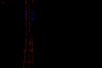
EXAMPLES
marking and light barriers of tall buildings
A - pattern for painting the upper part of the cover.
B - curved surface.
С - frame structure
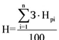
Note: H is less than 45 m for the examples in Figures 1 and 2. For taller structures, additional intermediate lights are required, as shown in Fig. 3.
Number of tiers of lights: N \u003d
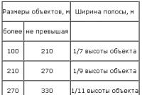
Table 1. Width of marking strips
Table 1
Construction height, m | The width of the line |
100 to 210 | 1/7 of object height |
210 to 270 | |
270 to 330 | |
330 to 390 | |
390 to 450 | |
450 to 510 | |
510 to 570 | |
570 to 630 |
Appendix N 3. Rules for shading obstacles
Appendix N 3
to the Federal Aviation Regulations
"Placement of marks and
devices on buildings, structures,
communication lines, power lines,
radio equipment
and other objects installed
for security purposes
flights of aircraft ", approved
by order of Rosaeronavigatsia
REGULATIONS
shading obstacles
1. General Provisions
An obstacle is considered to be "shaded" if it is located in the "shaded" area and does not cross the "shading" surface that passes through the top of the "shading" obstacle.
The "shaded" zone is formed only by fixed obstacles that are not light and brittle.
If an extended obstacle is only partially located in the "shaded" area, the remainder shall be considered as a normal obstacle to which the "shading" rules do not apply.
2. Internal horizontal and conical surfaces
The "shaded" area of \u200b\u200bpoint obstacles located within the inner horizontal and conical surfaces is a circle with a radius of 100 meters centered at the point of the obstacle. The "shading" surface passes through the top of the obstacle with a downward slope of 15% (Fig. 1).
The "shading" zone from extended obstacles located within the inner horizontal and conical surfaces is a 100 m wide strip along the perimeter of the obstacle. The "shading" surface passes over the top of the obstacle with a downward slope of 15% (Fig. 1).
The "shadow" from obstacles located near the boundaries of the approach surface, transition surfaces or take-off surfaces does not apply to the zones of these surfaces (Fig. 1).
The height of the "shading" surface at a distance L from the "shading" obstacle is
H \u003d Hp - 0.15L,
where Нп is the height of the "shading" obstacle;
L is the distance from the "shading" obstacle.
Distance L is determined by the plan of the inner horizontal and conical surfaces.
Fig. 1. To the formation of a "shaded" zone by obstacles located within
internal horizontal and conical surfaces:
1 - obstacle; 2 - "shading" zone; 5, 6 - obstacles in the "shaded" zone;
3, 4, 7, 8 - limiting surfaces.
3. Approach surface
Point obstacles located within the approach surface cannot be considered as "obstructions".
To draw a zone of "shadowing" from extended obstacles on the approach surface plan (Fig. 2), lines are drawn from the edges of the "shadowing" obstacle parallel to the lateral boundaries of the approach surface.
The "shading" surface is formed by two planes, one of which passes through the top of the "shading" obstacle with a downward slope of 15% towards the runway, the second - horizontally away from the runway (Fig. 2). The "shading" surface extends either to the point of intersection with the approach surface, or to the point at which the lines drawn from the edges of the "shading" obstacle (the lines forming the "shaded" zone) intersect, whichever is closer to " shading "obstacle (Fig. 2).
The height of the "shading" surface towards the runway is:
The height of the "shading" surface in the direction from the runway is:
Fig. 2. To the formation of a "shaded" zone by a continuous obstacle
within the approach surface:
1 - obstacle; 2 - "shading" zone.
4. Takeoff surface
Within the take-off surface, the "shading" zone is created by any fixed obstacle (point or extended, but not light and brittle) exceeding the inclined surface of 1.6% or 1.2%, as appropriate, established by the Airfield Serviceability Standards.
Its inner boundary starts from a line drawn through the top of the "shading" obstacle perpendicular to the axis of the take-off surface zone. The "shading" surface is formed by a plane drawn horizontally from the inner boundary of the area in the direction from the runway to the intersection with the take-off surface, which has a slope of 1.6% or 1.2%, as appropriate (Figure 3).
The height of the "shading" surface is: Н \u003d Нп.
Fig. 3. To the formation of a "shadow" zone within the take-off surface:
1 - obstacle; 2, 4 - limiting surfaces; 3 - "shading" surface; 5 - "shading" zone
Appendix N 4. Light barriers of buildings
Appendix N 4
to the Federal Aviation Regulations
"Placement of marks and
devices on buildings, structures,
communication lines, power lines,
radio equipment
and other objects installed
for security purposes
flights of aircraft ", approved
by order of Rosaeronavigatsia
dated November 28, 2007 N 119
Light barriers of buildings
A, B \u003d 45-90 m
C, D, E< 45 м
Appendix N 5. Characteristics of obstruction lights
Appendix N 5
to the Federal Aviation Regulations
"Placement of marks and
devices on buildings, structures,
communication lines, power lines,
radio equipment
and other objects installed
for security purposes
flights of aircraft ", approved
by order of Rosaeronavigatsia
dated November 28, 2007 N 119
CHARACTERISTIC
obstruction lights
A type | Peak intensity (in cd) at a given background brightness | Vertik. scattering angle. | Intensity (d) at given elevation angles when the fire block is positioned horizontally |
||||||||
probles- | More than 500 cd | Less than 50 cd | 10 deg. (e) | ± 0 deg. | |||||||
Low intensity type A (non- | Fast. glow | 10 min. | 10 min. |
||||||||
Low intensity type B (non- | Fast. glow | 32 minutes | 32 minutes |
||||||||
Medium intensity type A | Probless | 20,000 (b) | 20,000 (b) | 2000 | 3 deg, min. | 50% min. | |||||
Medium intensity type B | Probless | 2000 | 3 degrees min. | 50% min. | |||||||
Medium intensity type C | Fast. | 2000 | 3 deg, min. | 50% min / | |||||||
High intensity type A | Probless | 200000 | 20,000 (b) | 2000 | 50% min. | ||||||
High intensity type B | Probless | 100000 | 20,000 (b) | 2000 | 50% min. | ||||||
a) The number and location of low, medium or high intensity obstruction lights at each level to be marked is such that the object is indicated from all directions in the horizontal plane. If in any direction the light is obscured by another part of the object or by a nearby object, additional lights are provided on this object and they are positioned in such a way as to give a general idea of \u200b\u200bthe object to be illuminated. If a shaded object does not help define the general outline of the object to be shielded, it may not be installed.
b) Low intensity type C obstruction lights installed on vehicles used by the emergency services or security services are blue flashing lights, while lights installed on other vehicles are yellow flashing lights.
c) Beam angle is defined as the angle between two directions in a plane in which the intensity is 50% less than the intensity range indicated in columns 4, 5 and 6. The shape of the beam is not necessarily symmetrical about the elevation angle at which the peak intensity is reached.
d) The elevation angles (vertical) are determined relative to the horizontal plane.
e) Intensity in the direction of any horizontal radial as a percentage of the actual peak intensity in the direction of the same radial for each of the intensities indicated in columns 4, 5 and 6.
f) Intensity in the direction of any specifically defined horizontal radial as a percentage of the smaller value of the range of intensities indicated in columns 4, 5 and 6.
g) In addition to these values, the lights must be of sufficient intensity to be visible at elevation angles between + 0 deg and 50 deg.
h) Peak intensity should be achieved at a vertical angle of approximately 2.5 degrees.
i) Peak intensity should be achieved at a vertical angle of approximately 17 degrees.
fpm - flashes per minute; N / A - Not Applicable.
Appendix No. 6. Obstacle limitation surfaces
Appendix N 6
to the Federal Aviation Regulations
"Placement of marks and
devices on buildings, structures,
communication lines, power lines,
radio equipment
and other objects installed
for security purposes
flights of aircraft ", approved
by order of Rosaeronavigatsia
dated November 28, 2007 N 119
SURFACES
restriction of obstacles
Section A-A
Section B-B
Appendix N 7. Parameters of obstacle limitation surfaces
Appendix N 7
to the Federal Aviation Regulations
"Placement of marks and
devices on buildings, structures,
communication lines, power lines,
radio equipment
and other objects installed
for security purposes
flights of aircraft ", approved
by order of Rosaeronavigatsia
dated November 28, 2007 N 119
OPTIONS
obstacle limiting surfaces
Surface and its parameters | Runway direction for instrument approach | Runway direction for approach to minima of I, II, III categories |
||
Runway class | Runway class |
|||
Conical: | ||||
slope,% | ||||
height, m \u200b\u200b(relative to the inner horizontal surface) | ||||
Internal horizontal: | ||||
radius, m | ||||
height, m \u200b\u200b(relative to the aerodrome height) | ||||
Approach: | ||||
lower border length, m | ||||
distance from the runway threshold, m | ||||
first sector: | length, m | |||
slope,% | ||||
second sector: | ||||
________________ |
||||
slope,% | ||||
horizontal sector, length *, m | ||||
________________ * This length may vary depending on the height of the horizontal sector. |
||||
total length, m | ||||
Internal approach: | ||||
width, m | ||||
distance from the runway threshold, m | ||||
length, m | ||||
slope,% | ||||
Transient: slope,% | ||||
Internal transition: slope,% | ||||
Aborted landing: | ||||
lower border length, m | ||||
distance from the runway threshold **, m | ||||
________________ |
||||
discrepancy in each direction,% | ||||
Takeoff surface parameter * | Runway class |
||
________________ |
|||
Lower border length, m | |||
Discrepancy in each direction,% | |||
Length, m | |||
Upper border length, m | |||
Appendix N 8. Obstacle limitation surfaces, additionally established for landing at the minima of I, II and III categories
Appendix N 8
to the Federal Aviation Regulations
"Placement of marks and
devices on buildings, structures,
communication lines, power lines,
radio equipment
and other objects installed
for security purposes
flights of aircraft ", approved
by order of Rosaeronavigatsia
dated November 28, 2007 N 119
SURFACES
additional obstacle restrictions
for landing at the minimums of I, II and III categories
1 - internal transitional;
2 - internal approach;
3 - internal horizontal;
4 - interrupted landing.
Electronic text of the document
prepared by Kodeks CJSC and verified by:
Bulletin of normative acts
federal bodies
executive power,
12, 03.24.2008 (text of the order and rules);
On approval of the Federal Aviation Regulations "Placement of markings and devices on buildings, structures, communication lines, power lines, radio equipment and other objects installed to ensure the safety of aircraft flights"
| Document's name: | |
| Document Number: | 119 |
| Document type: | Rosaeronavigation order |
| Host body: | Rosaeronavigation |
| Status: | Acting |
| Published: | Bulletin of Normative Acts of Federal Executive Bodies, No. 12, March 24, 2008 (text of the order and rules) |
| Date of adoption: | November 28, 2007 |