Light protection is a required element. Light protection. Technical requirements for the foundations of antenna supports
3.3.1. Daytime markings and high-altitude obstacle lights are intended to provide information on the presence of these obstacles.
3.3.2. Obstacles are subdivided into obstacles located on the aerodrome territory and on the terrain within the airways.
3.3.3. The height of any obstacle should be considered its height relative to the absolute elevation of the terrain section on which it is located.
If the obstacle stands on a separate hill that stands out from the general flat terrain, the height of the obstacle is calculated from the foot of the hill.
3.3.4. Obstacles can be permanent or temporary. Permanent obstacles include fixed structures with a permanent location, temporary - all temporarily installed high-rise structures (construction cranes and scaffolding, drilling rigs, supports of temporary power lines, etc.).
3.3.5. Day marking is subject to:
all fixed permanent and temporary obstacles located on the aerodrome territory and airways, towering above the established obstacle limitation surfaces, as well as objects located in the aircraft movement and maneuvering zones, the presence of which may disrupt or worsen flight safety conditions;
located on the territory of air approach strips at the following distances:
up to 1 km from LM all obstacles;
from 1 km to 4 km with a height of more than 10 m;
from 4 km to the end of the Tollgate 50 m and more;
aTC, radio navigation and landing facilities regardless of their height and location;
objects with a height of 100 m and more, regardless of their location.
3.3.6. The marking of objects and structures should be carried out by enterprises, as well as organizations that build or operate them.
3.3.7. The need and nature of marking and lighting of the designed buildings and structures are determined in each specific case by the relevant civil aviation authorities when coordinating the construction.
3.3.8. Radio engineering facilities located on the aerodrome territory are subject to special marking and light shielding at the request of the DVT and the RF Ministry of Defense.
3.3.9. Obstacles that are especially dangerous for aircraft flights, regardless of their location, must have radio marking devices, the composition and tactical and technical data of which in each individual case must be coordinated with the DVT and the RF Ministry of Defense.
3.3.10. Objects that are shaded by taller marked objects are not subject to daytime marking.
Note. A shaded obstacle is any object or structure whose height does not exceed the height bounded by two planes:
horizontal drawn through the top of the marked object away from the runway;
inclined, drawn through the top of the marked object and having a downward slope of 10% towards the runway.
3.3.11. Day markings must clearly stand out against the background of the terrain, be visible from all directions and have two sharply different marking colors: red (orange) and white.
3.3.12. Objects that, according to their functional purpose, should be located near the LP and on the territory of the VFR, intended for servicing flights (ATC facilities, BPRM, DPRM, GRM, KRM, etc., excluding the control room):
a) the projection of which on any vertical plane has a width and height of less than 1.5 m, must be painted in one clearly visible color (orange or red) in accordance with Fig. 3.26, a;
b) having solid surfaces, the projection of which on any vertical plane is or exceeds 4.5 m and in both dimensions, should be marked with squares with a side of 1.5 - 3.0 m in the form of a checkerboard, and the corners should be painted in a darker color ( Fig. 3.26, b);
c) having solid surfaces, one side of which in the horizontal or vertical dimension exceeds 1.5 m, and the other side in the horizontal or vertical dimension is less than 4.5 m, should be painted with alternating color stripes 1.5 - 3.0 m wide The stripes are applied perpendicular to the larger dimension and the outer ones are painted in a dark color (Figure 3.26, c).
3.3.13. On the aerodrome territory of airports and air routes of the Russian Federation and MVL, structures with a height of up to 100 m are marked from the top point by 1/3 of the height with horizontal stripes alternating in color with a width of 0.5 - 6.0 m (Figure 3.26, d).
The number of stripes alternating in color should be at least three, and the outer stripes are painted in a dark color.
At the aerodrome territory of international airports and air routes of international importance, these objects are marked with horizontal stripes alternating in color of the same width from top to bottom (Fig. 3.26, e).
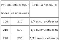
3.3.14. Structures with a height of more than 100 m, as well as structures of the frame-lattice type located at airports (regardless of their height) are marked from top to bottom with alternating stripes with a width taken in accordance with Table. 3.6, but not more than 30 m. The stripes are applied perpendicular to the larger dimension, the extreme stripes are painted in a dark color (Figure 3.26, f, g).
Table 3.6
Note. The stripes must be equal in width; the width of individual strips may differ from the width of the main strips by up to ± 20%
3.3.15. Light barriers should be provided for all obstacles specified in paragraphs. 3.3.2 - 3.3.14, in order to ensure safety during night flights and flights with poor visibility.
3.3.16. Obstruction lights shall be used for the light barrier. High-intensity lights are installed on especially dangerous obstacles.
3.3.17. Obstacles should have a skylight at the very top (point) and below every 45 m. The distances between intermediate levels should generally be the same.
On chimneys, the upper lights are placed 1.5 - 3.0 m below the pipe cutoff. Marking and lighting schemes are shown in Fig. 3.26, s, i. The number and location of obstruction lights on each tier must be such that at least two obstruction lights are visible from any direction of flight (at any azimuth angle).
Figure 3.26. High-rise obstacle marking scheme.
Note. A, B are equal to 45 - 90 m; C, D, D less than or equal to 45 m
3.3.18. Structures that exceed the angular planes of limiting the height of obstacles are additionally illuminated by double lights at the level of intersection of their planes.
3.3.19. At the upper points of the obstacle, two lights (main and backup) are installed, working simultaneously, or one at a time if there is a device for automatically turning on the backup fire in case of failure of the main fire. The automatic switch-on of the reserve fire shall operate in such a way that in the event of its failure, both obstruction lights remain on.
3.3.20. If in any direction the obstruction light is obscured by another (near) object, then an additional obstruction light must be provided on this object. In this case, the obstruction light, covered by the object, if it does not indicate obstacles, is not installed.
3.3.21. Long obstacles or a group of them, located close to one another, are illuminated at the highest points at intervals of not more than 45 m along the general contour. The highest points of the tallest obstacles within the enclosed contour and the corner points of an extended obstacle should be indicated by two obstruction lights in accordance with the rules provided for in 3.3.19 (see Fig. 3.26, i).
3.3.22. For extended obstacles in the form of horizontal networks (antennas, power lines, etc.) suspended between masts, obstruction lights are installed on masts (supports) regardless of the distance between them.
3.3.23. Tall buildings and structures located inside built-up areas are illuminated from top to bottom to a height of 45 m above the average building height.
In some cases, when the location of the tiers of obstruction lights violates the architectural design of public buildings, the location of the lights on the facade may be changed in agreement with the relevant departments of the Air Transport Department.
3.3.24. The light distribution and installation of obstruction lights should ensure their observation from all directions within the limits from the zenith to 5 ° below the horizon. The maximum luminous intensity of the obstruction lights should be directed at an angle of 4 - 15 ° above the horizon.
3.3.25. Obstruction lights must be of constant red color with a luminous intensity in all directions of at least 10 cd.
3.3.26. For light protection of detached obstacles located outside the zones of aerodromes and not having extraneous lights around them, white flashing lights can be used. The strength of the obstruction light in a flash must be at least 10 cd, and the frequency of flashes must be at least 60 per minute.
In the event that several flashing lights are installed at the facility, the simultaneous flashing shall be ensured.
3.3.27. The light barrier must be turned on for operation during the dark period of the day (from sunset to sunrise), as well as during the daylight hours with poor and impaired visibility (fog, haze, snowfall, rain, etc.).
3.3.28. Turning on and off the light barriers of obstacles in the aerodrome area should be carried out by the owners of the facilities and the ATC control center according to the specified operating mode.
In the event of failure of automatic devices for switching on the obstruction lights, it is necessary to provide for the possibility of manually activating the obstruction lights.
3.3.29. According to the power supply conditions, the means of light barriers of aerodrome obstacles should be classified as consumers of electricity of the first category.
The power supply of the obstruction lights is allowed through one cable line from the power supply buses of the power consumers of the first reliability category.
3.3.30. Obstruction lights and beacons must be powered by separate feeders connected to the switchgear busbars. Feeders must be provided with emergency (standby) power supply.
3.3.31. Light barriers should be securely fastened, safe service approaches and arrangements to ensure that they are accurately re-positioned after service.
3.3.32. Aerodrome sections not suitable for night operation should be marked with obstruction lights at the beginning and end of the sections. In this case, the taxiway lights are switched off on unsuitable sections of the taxiway. The obstruction light must be of constant radiation, red in color and have a luminous intensity of at least 10 cd.
3.3.33. Obstacle lights installed on objects located on take-off and landing courses of the aircraft (DPRM, BPRM, KRM, etc.) must be placed on a line perpendicular to the runway axis, with an interval between lights of at least 3.0 m. The light must be of a double structure and a luminous intensity of at least 7 cd.
Similar information.
Towers and masts of communication facilities, in accordance with the international and Russian requirements for aviation security ICAO (International Civil Aviation Organization) and IAC (Interstate Aviation Committee) must be equipped with obstruction lights. With an increase in the number of base stations of operators, the cost of their equipment and maintenance increases. That makes it necessary to reassess the effectiveness and feasibility of using previously developed lighting systems.
Typically, a light barrier system includes: obstruction lights (ZOM), surge protector, lamp monitoring device, DC / AC inverter, power supplies.
The main element of lighting systems that determines their characteristics (energy consumption, reliability, operating costs and equipment cost) is the light source. In accordance with the law on energy efficiency adopted by the State Duma, Russia has banned the sale and production of incandescent lamps with a power of over 100 watts in 2011. A similar ban on lamps with power above 75 W will come into effect in 2013, production will be completely discontinued in 2014. Currently, telecom operators are replacing incandescent lamps with LEDs, which can significantly reduce operating costs due to the low energy consumption and long life of LED lamps. Comparative data on lamps for ZOM are given in Table 1.
As can be seen from the data given in Table 1, LED lamps (LEDs) have a significant advantage not only over incandescent lamps, but also energy-saving gas-discharge lamps. their only drawback is the higher price, which will decrease with the growth of their production. The most common types of LED bulbs are available in both 220V AC and 48V DC. When using the latter, equipment costs are reduced, since they do not require the installation of an additional DC / AC inverter to power them. There are several options for decisions on catering for SOPs (Table 2).
Having weighed all the pros and cons, we can come to the conclusion that the best option is to power the COM from the DC electrical installation of the communication object. At the same time, it is necessary to take into account the possibility of introducing overvoltages that occur when lightning strikes a high-rise object, which can lead to damage to the equipment of base and radio relay stations, communication disruptions. One of the main requirements for the light barrier system is the mandatory backup of power supply, since in the event of a loss of the main power supply, a high-altitude object at night or in conditions of poor visibility can pose a danger to aircraft. This requirement is reflected in the Manual for the operation of civil aerodromes of the Russian Federation (REGA RF-94).
An important consequence of the use of LED lamps is the possibility of changing the maintenance schedule - namely, not the planned replacement of lamps, but replacement after failure. In addition, it is desirable to be able at any time to determine how many SDLs from the number installed on the mast have failed, which will make it possible to make a decision on the urgency of replacing burned out LED lamps. Obviously, the full benefits of switching to SDL in light barriers can only be realized if a system for monitoring their health is used, especially at remote sites where constant visual control is impossible.
The tasks of protecting COM power circuits and monitoring the state of obstruction lights were set by the Logic Element company to COMMENG DEVICES engineers, and were implemented in the UZK-COM system. The complex includes two modules: protection of power circuits of the zone fence of the masts and control of the consumed current. Let's consider some of the technical solutions incorporated in the developed system.
Power circuit protection
The well-known characteristics of the load and the small currents consumed by the lighting equipment made it possible to use a highly efficient two-stage protection circuit included in the break of the supply cable. the device implements a protection circuit with a choke decoupling, providing speed and protection against high-power current pulses. Depending on the expected level of electromagnetic influences (the height of the mast, the number of thunderstorm days in a year, the characteristics of the communication object), power circuit protection devices of various classes (UZTsP-ZOM II or III) can be used, which are necessarily included in the equipment complex.
Monitoring the status of obstruction lights
As a rule, complete or partial failure of the SDL is accompanied by the cessation or reduction of current consumption, proportional to the decrease in luminosity. Exposure to high input voltages and high voltage pulses does not cause short circuits in the lamps. A very important property of LED lamps is the stability of current consumption, when the input voltage changes over a fairly wide range, which is provided by the current drivers installed in them. thus, it is possible to monitor the SDL health by measuring the current consumed by them. In this case, the level (or levels) that indicate a violation in the work of the COM can be selected based on the parameters of a particular object. Information about the disconnection of a given number of lamps is converted into a logical signal and, using the opto-relay contacts, is transmitted to the monitoring system available at the facility. The principle of control is quite simple, however, in real-life conditions, various additional factors must be taken into account, for example, the energy consumption of the heaters for the shades, which serve to prevent icing. the use of an analog control circuit increases the reliability of the solution implemented in the control device for the consumed current UKPT-ZOM.
The modules are installed in a standard electrical enclosure (Fig. 1), and can also be directly mounted on site in a cabinet or rack with electrical equipment.
The obtained characteristics of the light barrier protection and control system:
- low power consumption (< 1Вт);
- power supply from standard DC control unit;
- preventing the introduction of impulse noise in the secondary power supply circuit of the equipment, with overvoltages of a natural (lightning) and industrial nature;
- remote control of LED lamps health;
- issuing an alarm signal, both when the current drops below the set threshold, and when the current overload;
- automatic return to working condition after overload termination;
- the possibility of two-stage overvoltage protection
- service life not less than 40,000 hours
- the ability to automatically connect backup power.
The article outlines an already implemented device. Currently, a group of specialists from several enterprises continues to work on improving both the lighting monitoring system and the light sources themselves. On the basis of common principles of construction, element base, standardized units, each operator can be offered an optimal solution for him.
TECHNICAL REQUIREMENTS FOR INFRASTRUCTURE ELEMENTS OF RADIO SUBSYSTEM OBJECTS.
Abbreviations
JSC- antenna support (tower, mast, pole), installed on the ground.
TU -technical conditions
Paintwork- paintwork
RK- junction box
q day marking, light protection, lightning protection and AO grounding;
q fencing and planning of the territory of the JSC site;
Infrastructure elements must comply with the requirements of SNiP, GOST, instructions, regulatory documents for the design and construction of high-rise buildings, documents of other departments operating in Ukraine and in.
1. TECHNICAL requirements for ANTENNA SUPPORT FOUNDATIONS
1.1 General
1.1.1 The foundations of the JSC and containers must be manufactured in accordance with the requirements of the project, as well as the following regulatory and technical documents:
q SNiP 2.02.01-83. "Foundations of buildings and structures";
q SNiP 3.03.01-87. "Supporting and enclosing structures";
q SNiP 3.02.01-87. "Earthen structures, foundations and foundations";
q GOST 5781-82. “Hot rolled steel for reinforcing reinforced concrete structures. Technical conditions ";
1.1.2 Foundations for JSC, depending on the engineering and geological conditions and economic feasibility, can be of the following types:
q monolithic reinforced concrete (belt, free-standing, prefabricated);
q pile (driven reinforced concrete, drilling, rammed, injection, screw) with reinforced concrete or metal grillage;
1.1.3 For the installation of the container, non-subsiding foundations should be used (with a depth below the freezing level of the soil).
1.2 Technical requirements for the foundations of antenna supports
1.2.1 Geometrical dimensions, plan-height position of foundations must correspond to the project.
1.2.2 The strength of concrete foundations must be at least 200kg / cm2 (compressive strength class - B20, B22.5, B25).
1.2.3 The grade of concrete for frost resistance (F) and water permeability (W) must correspond to the project.
1.2.4 In case of low bearing capacity of soils, a crushed stone pad with a thickness of up to 40 cm with layer-by-layer compaction and with bitumen pouring to a depth of at least 10 cm or in another way should be made to strengthen the base of the foundations.
1.2.5 Before reinforcing the foundations, concrete preparation of class B 7.5 concrete with a thickness of 10 cm should be made.
1.2.6 Reinforcement should be carried out in accordance with the project with hot-rolled thermomechanically hardened reinforcement of grade A III in accordance with GOST 5781-82. The reinforcement rods at each intersection must be tied with a knitting wire (electric welding is allowed along the outer perimeter of the reinforced mesh).
1.2.7 Concreting should be carried out in accordance with the project and SNiP 3.03.01-87.
1.2.8 Concrete cover thickness for reinforced mesh should be appropriate for the design.
1.2.9 All surfaces of foundations in contact with the ground are painted with hot bitumen mastic in two layers or other similar waterproofing material according to the project.
1.2.10 Backfilling of the pits of free-standing foundations and monolithic grillages should be performed with non-subsiding soil with layer-by-layer compaction
before p \u003d 1.65 t / m³.
1.2.11 Installation of steel structures of JSC is allowed to be carried out after the concrete reaches at least 50% of the design strength.
1.2.12 The following types of piles can be used for the construction of pile foundations:
q driven with a section of 20x20cm, length 3-6m;
q driven with a section of 25x25 cm, length 4.5-6 m;
q hammered in cross-section 30x30cm, length 3-12m;
q hammered in cross-section 35x35cm, length 8-16m;
q driven with a section of 40x40cm, length 13-16m;
q reinforced concrete shell piles, buried by vibratory hammers with excavation and filled partially or completely with concrete mixture;
q rammed concrete and reinforced concrete, arranged in the ground by placing a concrete mixture in boreholes, formed as a result of forced squeezing (displacement) of the soil;
q reinforced concrete drilling, arranged in the ground by filling the drilled holes with concrete mixture or installing reinforced concrete elements in them;
q screw.
1.2.13 Driven piles with a length of up to 10 m, under-loaded by more than 15% of the design depth and piles of greater length, under-loaded by more than 10% of the design depth, but giving a failure equal to or less than the calculated one, should be examined to find out the reasons that impede the immersion. The design organization makes a decision on the possibility of using existing piles or driving additional piles (SNiP 3.02.01-87). Piles with a failure greater than the calculated one should be subjected to control finishing after "resting" in the ground in accordance with GOST 5686-78. In the event that the refusal during checkout addition exceeds the calculated one, the design organization must establish the need for control tests of piles with a static load and adjustments to the design of the pile foundation or its part. Piles with transverse and oblique cracks with an opening width of more than 0.3 mm must be reinforced with a reinforced concrete frame with a wall thickness of at least 100 mm or replaced. In the event of pile undermining or damage to the heads during driving, the pile heads must be cut off by methods that exclude the violation of the protective layer of the concrete of the pile below its cut.
4.2.14 Embedding of piles into reinforced concrete and metal grillages should be carried out in accordance with the project, while the reinforcement released from the piles should be thoroughly cleaned and connected to the reinforcing mesh of the reinforced concrete grillage with knitting wire, and with the metal grillage - by electric welding.
1.3 Technical requirements for the installation of anchor embedded parts and support plates of antenna supports.
1.3.1 Installation of anchor embedded parts should be carried out on concrete preparation made of concrete of class B7.5, 10 cm thick. In the places where the embedded parts are installed, careful vibration should ensure that the bottlenecks are filled with a concrete mixture.
1.3.2 The accuracy of the installation of anchor embedded parts should be verified by geodetic measurements. A jig should be used to fix the relative position of the anchor rods.
1.3.3 The accuracy of the installation of the base plates of the AO must be ensured by the vertical adjustment of the anchor rod nuts.
1.3.4 The concreting of the base plates should be carried out after the installation, alignment and fastening of the first tier of the AO with the provision of drainage of sediments.
1.3.5 The length and number of studs of anchor embedded parts should be determined by the project.
1.4 Requirements for base station container foundations
1.4.1 The base station container should be located next to the AO at a height of 0.5-0.7 m from the ground.
1.4.2 To install the container, foundations can be used using materials:
q freestanding metal pillars made of pipes 219x8mm in accordance with GOST 8732-78 or reinforced concrete piles with a section of 20x20cm;
q monolithic reinforced concrete foundations resting on the base plate of the AO foundations;
q I-beams resting on the walls of the AO strip foundation.
1.4.3 Metal pillars should be installed at a depth below the freezing level of the ground. The lower part of each pillar should be embedded in a monolithic reinforced concrete base 300-400mm thick. In accordance with the requirements of GOST 9.602-89, anti-corrosion protection of pillars must be performed, including:
q coating with hot bitumen in 2 layers;
q pasting with adhesive PVC-L tape with a thickness of 0.4 mm (TU) in two layers;
q application of a protective wrapper (wrapping paper in accordance with GOST 8273-75).
1.4.4 Free-standing monolithic foundations must be made in accordance with the requirements for AO foundations.
1.4.5 Fastening the container to free-standing metal pillars, reinforced concrete piles, monolithic reinforced concrete foundations should be carried out using load-bearing I-beams in accordance with the project. Fastening of the beams to the embedded parts and the container to the beams is carried out using electric welding with E42 electrodes. After installation, the beams are painted in two layers with PF-131 pentaphthale enamel on the GF-021 soil. Incomplete support of the container on the supporting beams is not allowed.
2. TECHNICAL requirements for metal structures of ANTENNA SUPPORTS
2.1 General
2.1.1 Steel structures of JSC must be manufactured in accordance with the requirements of the project, as well as the following regulatory and technical documents:
q OST 45.27-84. “System of labor safety standards. Metal masts and towers ”.
q SNiP ІІІ-18-75
2.1.2 In accordance with the terminology, AO includes: steel towers, masts and columnar supports (reinforced concrete and steel pillars).
2.1.3 By design, steel towers can be: triangular and tetrahedral, pyramidal, prismatic and combined. Steel masts can also be triangular and tetrahedral, usually of a prismatic type.
2.1.4 For the manufacture of towers and masts, materials can be used:
q round steel pipe;
q square steel pipe;
q steel corner;
q round steel;
q combined (a combination of the above types of rental).
2.1.5 Columnar supports can be:
q steel hollow polyhedral or round, consisting of separate sections;
q reinforced concrete hollow.
2.1.5 For the manufacture of columnar supports, materials can be used:
q rolled steel sheets, steel pipes of design thickness;
q Reinforcing steel, prestressed concrete.
2.1.6 JSC should provide:
q given bearing capacity;
q given deformability;
q given height;
q wind load (correspond to the wind region of the AO location);
q ice and snow load (correspond to the ice and snow area of \u200b\u200bthe AO location);
q seismic stability (depending on the seismic region of the AO location).
2.1.8 The quality of steel used for the manufacture of steel structures of JSC must comply with the requirements of the project and be certified by the certificate of the metallurgical enterprise to which the steel was supplied. If the certificate is found to be inconsistent with the marking of the rolled metal or in its absence, studies are carried out by input control in the required volume, provided for by the relevant standards.
2.2 Technical requirements for the equipment of antenna supports
Antenna supports must be equipped with elements and devices that provide maintenance personnel with the safety of lifting and lowering from the support. Antennas, mechanisms, electrical equipment and other devices located on the support and requiring maintenance must be provided with safe access from stairs, platforms.
2.2.1 AO equipment should include:
q ladder-ladder with a guardrail in the form of arcs, which provides maintenance personnel with a safe ascent to and from the AO, in accordance with the industry safety standard OST 45.27-84;
q structures for fastening cables - strips of metal strip 40x4mm or round steel Ø16.0mm with a pitch of 0.6-0.7m. Fastening of the COM cable to the strips should be carried out with metal clamps);
q pipe stands for BS antennas with horizontal or vertical spacing of at least 3.5 m for antennas in the 900 MHz range and at least 2.0 m for antennas in the 1800 MHz range (tube stands for BS antennas must be made of pipes with a diameter of 89x6 mm and have a length of at least 2.9 m) ;
q pipe stands (main and reserve) for PPC antennas made of pipes with a diameter of 114x6mm and a length of at least 1.5m;
q structural elements for fixing fixing (adjusting) rods in the places of installation of RRS antennas with a diameter of 1.2 m and more;
q transitional and technological sites for recreation and maintenance of BS and RRS antennas.
2.2.2 Requirements for a step-ladder and transitional technological platforms:
q the width of the stairs must be at least 0.45 m, the distance between the steps - no more than 0.35 m, the steps must be made of round steel with a diameter of 20 mm;
q arcs of the fence should be located at a distance of no more than 0.8 m from each other and be interconnected by at least three longitudinal rods made of round or strip steel, the distance from the ladder to the arc should not be less than 0.7 m and more than 0, 8 m with an arc radius of 0.3-0.4 m;
q with ladders more than 10m high, rest areas should be arranged every 6-8m (in some cases, with a span of 10-20m, two guides are installed parallel to the ladder bowstring, a rod with a diameter of 20mm to alternately fasten the safety belt carabiners. more than 4m in a checkerboard pattern);
q with a span of more than 20m, the stairs must be equipped with FABA-type fixed belay systems;
q Recreation areas, as well as for servicing antennas and light-signaling devices COM, must be at least 0.5x0.5m in size, equipped with hatch covers that can easily and conveniently open upwards, a fence with a height of at least 1.1m (the number of fence elements must be at least three, including the handrail, with a distance from the platform deck 0.1m; 0.6m; and 1.1m);
q the location of sites should ensure ease of maintenance and unimpeded access to antennas and light-signaling devices COM;
q in columnar supports made of steel pipes with a diameter of no more than 1.22 m, it is allowed to arrange rest areas with a step of up to 12 m, while every three spans, but no more than 36 m, the pipes must have a continuous overlap with a hatch device of at least 0, 5x0.5m;
q decking of platforms should be made of steel corrugated or perforated sheets with holes no more than 20 mm in diameter (in this case, the edges of the decking along the contour of the hatch should be framed with a metal corner in order to prevent injury to the service personnel);
q the hatch to prevent access to the tower must have loops for the lock;
q All hatch covers must be securely locked in the open position.
2.3 Technical requirements for metal structures of antenna supports
2.3.1 AO should be designed for external influences characteristic of the climatic zones of its location, for loads from its own weight, equipment weight and installation loads.
2.3.2 The safe operation period of the JSC must be at least 40 years from the moment of its installation, subject to the periodic restoration of the anti-corrosion coating of metal structures and compliance with the operation requirements in accordance with the "Instruction for the operation of antenna structures of radio relay communication lines" (01/14/1980).
2.3.3 Steel structures of JSC must be manufactured with accuracy, excluding any power operations during their control assembly at the factory and during installation. Pulling, thrusting, bending, impact and other force effects leading to the creation of a stress-strain state in metal structures, work hardening, cracks (or prerequisites for cracks) should be completely excluded. It is not allowed to widen the holes for bolted joints using electric welding.
2.3.4 Flange connections should ensure tight contact of the planes of adjacent flanges. In a bolted flange joint, the feeler gauge is 0,3 mm should not reach the outer diameter of the chord pipe by 20 mm around the entire perimeter, and the local gap at the outer edge around the circumference of the flanges of two adjacent sections should not exceed 3 mm. All contacting surfaces of the flanges must provide electrical contacts of the AO lightning protection system. They should be temporarily coated to prevent corrosion in transit.
2.3.5 All welds must comply with the requirements of SNiP 3.03.01-87 (Table 41. The presence of metal burn-throughs, lack of penetration is unacceptable... Welds generally need to be made in the factory. In the case of welding work at the construction site, the seams must be even, with the dimensions of the legs determined by the project, processed, cleaned of slag and scale, primed and painted.
2.3.6 The internal cavities of all elements made of round pipes must be tested for tightness and tightness of welded seams by an excess air pressure of 0.4-0.5 atm. After obtaining satisfactory test results, the technological holes must be welded with tight seams. It is necessary to fill the flange joints with bitumen mastic.
2.3.7 All AO structures must undergo a control assembly and be marked in accordance with the designations (indexes and codes) established on the structural design drawings. The marking of assembly units must include the information necessary for the correct assembly of the AO and the identification of elements during operation, in accordance with the assembly wiring diagram.
2.3.8 The system of protection of steel structures of JSC from corrosion should be carried out in accordance with SNiP 2.03.11-85 "Protection of building structures from corrosion". Particular attention should be paid to the quality of surface preparation, subject to corrosion protection (removal of burrs, welding spatter, flux residues, complete cleaning of welded seams, rounding of sharp edges, removal of dirt and degreasing the surface with white spirit, removal of mill scale and rust by sandblasting (shot blasting) to 2nd degree of purification according to GOST 9.402-80.
2.3.9 Depending on the operating conditions of the support, in accordance with Table 29 and Appendix 15 of SNiP 2.03.11-85, the group, type, number of coating layers and the total thickness of the AO paint-and-lacquer coating must be determined.
2.3.11 Acceptance of the quality of LKP JSC should be carried out by the customer in accordance with GOST.
2.3.12 The results of factory acceptance control of JSC structures should be entered into the certificate for the manufacture of steel structures. The certificate must also include data on the steels and welding consumables used, the results of the inspection of welded joints, the results of the control of anti-corrosion coatings, and the results of the control assembly. The certificate for steel structures must be accompanied by certificates for rolled steel used in the manufacture of metal structures.
2.4 Technical requirements for the installation of metal structures of antenna supports
2.4.1 Marking of bolts and nuts should be carried out in accordance with GOST 1759.0-87, GOST and comply with the project. Fasteners must have a manufacturer's certificate indicating the strength class, type of metallization coating and its thickness. The bolt heads must bear the manufacturer's stamp and the strength class designation.
2.4.2 Bolted fasteners must be protected against corrosion by a thermal diffusion zinc coating or cadmium, zinc chromated coating in accordance with GOST 9.303-84. The thickness of the applied metallization coating (thermal diffusion or galvanic) must correspond to class 9 (9 microns). All hardware must be painted. The use of hardware without a protective coating is not allowed.
2.4.3 Before the pre-assembly of the steel structures of a joint-stock company, a sampling and defect identification of hardware must be made that does not have a stamp indicating the strength class, as well as without a metallized protective coating.
2.4.4 Bolted joint assembly shall include: a bolt, one washer on each side of the tightened surfaces, a nut and a locknut. The bolt should be tightened with a loose lock nut with an assembly wrench. Locknuts should be tightened after all bolts have been installed in this connection. In addition, the use of a spring washer is allowed as a way to prevent self-loosening of the nuts. In this case, a flat washer is installed under the head of the bolt; a flat washer is not installed under the spring washer. The decision to prevent self-loosening of the nuts - setting a lock washer or locknut - must be reflected in the project. The tightness of the screed of the AO metal structures is checked with a 0.3mm thick gauge, which should not pass between the assembled parts to a depth more than 20mm within the area bounded by the puck. After tightening, the heads and nuts of the bolts must tightly (without gaps) touch the planes of the washers or elements of metal structures, and the bolt rod should protrude from the nut not less than 3mm.
It is not allowed to jointly install a spring washer and a round washer under the bolt nut, install more than two round washers under the bolt nut, lock the nuts by driving the bolt threads or welding them to the bolt rod (SNiP 3.03.01-87).
2.4.5 The thickness of the guy ropes, the types and number of clamps, shackles, turnbuckles, tensioners for steel masts must comply with the project and the requirements of the regulatory and technical documentation. The values \u200b\u200bof the forces in the guys must correspond to the tension tables attached to the project and checked using a strain gauge.
2.4.6 Checking the verticality of the mounted AO should be performed after completion of its installation. The results of monitoring the position of the installed sections vertically and in plan (twisting) should be shown on the executive scheme of geodetic control. The deviation of the shaft axis from the design position should be no more than 0.001 (for a tower and a pillar), no more than 0.0007 (for a mast) of the height of the point to be verified above the foundation.
2.4.7 Verification of the verticality of the AO shaft axis is carried out in accordance with Standard ST-047-2 “Requirements for geodetic control of antenna supports”.
3.TECHNICAL REQUIREMENTS FOR DAY MARKING, LIGHTING, LIGHTNING PROTECTION AND EARTHING OF ANTENNA SUPPORTS
3.1 General Provisions
3.1.1 Day marking, lightning, lightning protection and grounding of AO must be performed in accordance with the requirements of the project, as well as the following regulatory and technical documents:
q "Air Code of Ukraine";
q "Certificates of vimogi to civil aerodromes of Ukraine";
q ICAO Requirements Annex 14, International Civil Aviation Organization;
q "Regulations on the Victory of the Poetryan Space of Ukraine";
q "Instructions on the device for lightning protection of buildings, structures and industrial communications", RD 34.21.122-87;
The need and nature of daytime marking and light shielding of the projected JSC are determined by the relevant military and civil aviation authorities when coordinating the construction.
3.2 Technical requirements for daily marking of antenna supports
3.2.1 AO day markings should clearly stand out against the background of the terrain, be visible from all directions and have two sharply different marking colors: red (orange) and white. The color of the paint is determined according to the RAL-K7 color catalog (3020, 3024-red, 2004, 2005-orange, 9010, 9016-white).
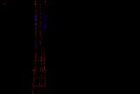
3.2.2 Day marking should be carried out with horizontal stripes of red (orange) and white colors alternating in color with a width of 0.5-6.0 m for the entire height of the AO (Fig. 1). The stripes must be equal in width. The width of individual lanes can vary from the width of the main lanes to + twenty%. When painting the steel structures of JSC in the factory, sectional painting is allowed.
Figure: 1. Day marking
3.2.2 The number of alternating stripes must be at least three.
3.2.3 The upper and lower marginal stripes of the day marking shall be painted dark (red or orange).
3.3 Technical requirements for light barriers of antenna supports
3.3.1 Light barriers are provided at the AO to ensure safety during night flights and flights with poor visibility. For light protection, obstruction lights (light signaling devices) of the ZOM type are used.
3.3.2 Light barrier elements should be located at the highest point of the AO and below every 45m. The distances between intermediate tiers, if possible (depending on the location of the sites), should be the same (Fig. 2).
3.3.3 The placement of COM lights on AO metal structures should be performed in such a way that at least two lights on each tier can be seen from any direction in the horizontal plane. For this purpose, the lights must be removed from the AO projection on outboard brackets.

Figure: 2. Lighting of JSC
3.3.4 At least three lights shall be installed on each tier.
3.3.5 During the construction of an AO with a height of less than 45 m (pillar type) subject to marking and light protection, according to the conclusion of the aviation authorities, two lights (main and backup) can be installed at the top points, operating simultaneously, or one at a time if there is a device for automatic switching on of reserve fire (in case of failure of the main fire). The automatic switch-on of the reserve fire must work in such a way that in the event of its failure, both lights remain on (Fig. 3).

fig. 3 Light protection JSC N<45 м (столб)
3.3.6 Consumers of the AO light barriers located in the aerodrome area and on the routes of local overhead lines, according to the power supply conditions, should be categorized as category I consumers according to the PUE and REGA classification. It is allowed to supply the obstruction lights through one cable line from the buses of electrical receivers of category I in terms of the reliability of power supply in accordance with the requirements of the REGA.
3.3.7 Obstacle lights should be powered by separate feeders connected to the switchgear busbars. Feeders must be provided with emergency (backup) power supply. In the event of a failure of the main power supply, a decrease in voltage or its short-term disappearance, an automatic activation of an emergency power supply should be provided. Loss of power supply should be no more than 60 seconds.
3.3.8 Consumers of the AO's light protection located outside the aerodrome area and the MVL routes may be supplied with electricity from those power supply sources (with the same reliability category) from which the building (structure) is powered.
3.3.9 In order to improve the reliability of the operation of the lights of the light barriers, they should be connected to different phases of the supply feeder connected to separate machines, so that on each tier there is at least one light connected to another phase.
3.3.10 The power cable for the light protection lights should have a light-shielding coating against solar radiation and armor to protect against potential drift in the event of a lightning strike.
3.3.11 As a COM cable, a five-core armored cable with multi-colored cores of the type VBbShv 5x2.5 (stand-by) -0.66 is used to the junction box and a three-core cable of the type VBbShv 3x1.5 (stand-by) -1 from the junction box to the COM devices.
3.3.12 The COM cable, when laying, should not have twists, insulation faults, sharp bends, should exclude unnecessary compression with clamps or staples.
3.3.13 The COM cable should be laid on separate, specially designated brackets. In the case of laying the COM cable along kabelrost together with the feeders of antenna devices, the spacing should be at least 10 cm. Fastening of the COM cable should be done with metal clamps (brackets) to the steel structures of the AO with a pitch of 0.6-0.7 m, on sites - with mounting tape or metal clamps (pitch-0.6 m).
3.3.14 Laying the cable from the AO to the control room container should be carried out along a 50x50x5mm angle, fixed to the AO with clamps, and to the container by welding.
3.3.15 Fastening of the PK (KZNS type) should be performed by electric welding, cable entries should be located horizontally.
3.3.16 When entering the RK, a drop-intercepting loop must be made on the COM cable (the cable is bent to prevent ingress and accumulation of moisture).
3.3.17 All cable entries (outputs) in the RK must be sealed using silicone sealant. RKs must be equipped with oil seals and drain holes. 4.3.18 The connection of the cable armor shall be made by means of bolted joints with the body of each COM light-signaling device and each RK.
3.3.19 When installing the AO lighting system, reliable contact connections must be provided. It is recommended to connect no more than two conductors to each bolt (screw) or pin terminal (GOST).
3.3.20 The location of the COM and RK lights should ensure ease of maintenance and comply with the project. The distance from the base of the service platform to the COM lights or junction boxes must be at least 0.8 m. The COM lights should be on constantly. Installation of a light relay is prohibited.
3.3.21 Light distribution and installation of obstruction lights should ensure their observation from all directions within the range from zenith to 5 degrees below the horizon. The maximum luminous intensity of the obstruction lights should be directed at an angle of 4-15 degrees above the horizon.
3.3.22 Obstruction lights should be of constant red color with luminous intensity in all directions of at least 10 cd.
3.3.23 LED light-signaling devices must be installed in the COM devices for light protection of JSCs that meet the requirements of REGA, IAC, Ministry of Defense of Ukraine and the International Civil Aviation Organization (ICAO). Devices must have a conclusion for the use of Ukraerorukh. The use of appropriate lighting devices should be defined by the project.
3.4 Technical requirements for lightning protection and grounding of antenna supports
3.4.1 Lightning protection should be carried out by grounding the support. AO metal structures are used as down conductors. Lightning rods must be installed on the upper section of the AO and attached at the highest point, one to each of the belts and have a height of at least 1.5 m. Lightning rods must be made of round steel with a diameter of 16-25 mm and rise above the top edge of the antenna by at least 0.4 m.
3.4.2 All elements of the metal structures of the AO technological sites, on which the antenna equipment and electrical equipment are located, must have reliable electrical contact with the ground loop.
3.4.3 To ensure reliable electrical contact of lightning rods and electrical equipment (located at the AO) with the ground loop, welded joints should be provided using jumpers of various types, welded and painted during installation in the nodes established by the project.
3.4.4 Connection of PE - conductor with cases of junction boxes and COM devices should be made using bolted connections.
3.4.5 AO grounding should be carried out by connecting its support part with a ground loop, consisting of 4-6 ground electrodes made of steel corners 50x50x5mm, and interconnected by a grounding steel bus 40x4mm. The grounding bus must be welded to the AO belts after the first section is installed. Welding should be overlapped along the contour.
3.4.6 The grounding of the container must be performed at 2 points, from opposite sides on a diagonal, with grounding buses welded along the contour, with an overlap with a continuous seam of at least 100 mm in length.
4. TECHNICAL REQUIREMENTS for the FENCING and PLANNING of the ANTENNA SUPPORT site area
4.1 General
4.1.1 Fencing and planning of the territory of the JSC site must be performed in accordance with the requirements of the project, as well as the following regulatory and technical documents:
q SpiP III-10-75. Territory improvement;
4.2 Technical requirements for JSC fencing
4.2.1 The metal fencing of the JSC site is designed to protect against the penetration of unauthorized persons into its territory. AO fencing must be manufactured and installed in accordance with the project.
4.2.2 Fencing of the AO site should be a metal structure consisting of sections that must be attached to the posts. The fence must have a wicket. At the top of the fence, brackets should be installed to which galvanized barbed wire is attached. The distance from the AO foundation to the fence must be at least 1m.
4.2.3 Fencing sections should be made of steel profiles 15x15mm, 15x20mm, 25x25mm. The profiles of the fencing sections must be attached to a corner of at least 40x40x4mm in size, or to a 40x4mm steel strip using electric welding with a pitch of 150mm. The fence posts must be made of a pipe with a diameter of at least 76x3mm or channel # 10. The upper ends of the pillars made of pipes must have plugs made of sheet steel and welded with a continuous seam. The fence posts must be concreted into the ground to a depth of at least 1m. The height of the fence must be at least 2500mm. The distance between the bottom edge of the fence and the ground should be no more than 100mm.
4.2.4 The width of the wicket must be at least 1000mm. The wicket must be attached to the fence with hinges and have padlock loops. The gate should be mounted on the right hinges, open outward of the platform and, if possible, be located opposite the entrance to the container.
4.2.5 Brackets for fastening barbed wire should be made of a steel bar (metal corner) with a diameter of 16mm and a length of at least 400mm. The brackets must be welded to the fence posts along the entire perimeter, with a step of at least 1.5 m and have an inclination towards the inside of the site by 45-60 ° from the horizon or be located vertically. The barbed wire must be securely attached to the brackets and mounted in two rows. The distance between the threads should not exceed 150mm. The bottom thread of the wire should be 150mm from the top of the fence. Tensioning of 3 rows of barbed wire is allowed. In this case, the distance between the threads may decrease and the length of the brackets may increase. Barbed wire should not have sagging.
4.2.6 The fencing of the JSC site must be hot-dip galvanized.
4.3 Technical requirements for the planning of the site of the antenna supports
4.3.1 After the installation of the AO, the planning, improvement of the AO site and the territory adjacent to the fence should be performed. The decisions on the planning and improvement of the site and the area adjacent to the fence should be reflected in the project.
4.3.2 Site planning should be carried out with crushed stone on a sand cushion with a thickness of at least 10 cm. The thickness of the crushed stone layer must be at least 10 cm. The distribution of crushed stone and sand should be carried out only from high to low marks. Backfilling of the site should be carried out with crushed granite (it is allowed to use lime rocks, pebbles) rocks with a fraction of 20-40 mm. The site must have slopes of at least 3% from the center of the site to its edges. Soil subsidence is unacceptable.
4.3.3 If necessary, for the outflow of atmospheric and melt water, it is allowed to install drainage grooves. The grooves should be located at a distance of no more than 3m from one another, they must be cut along a slope or at an angle of 30-60 ° to the direction of the slope. Water drainage along the grooves is carried out 3 m from the site boundaries. The slope of the grooves should follow the slope of the graded surface, but not less than 2%.
4.3.4 The site should be equipped with slopes to prevent erosion or crumbling of the layout. Slopes should be carried out with soil compaction at a distance of no more than 0.5 m from the site fence. If the height of the embankment is more than 0.5 m, then the slopes must be reinforced with sod or other means. Sloughing and erosion of soil of slopes are unacceptable.
Chapter 2.12. ELECTRIC LIGHTING
2.12.1. The requirements of the Rules set forth in this chapter apply to electric lighting devices for Consumers, premises and structures, residential and public buildings, open spaces and streets, as well as advertising lighting.
2.12.2. Work and emergency lighting in all rooms, workplaces, open spaces and streets must provide illumination in accordance with the established requirements.
The working and emergency lighting fixtures used during the operation of electrical installations must only be factory-made and comply with the requirements of state standards and technical conditions.
2.12.3. Emergency lighting luminaires should be distinguished from working lighting luminaires in signs or colors.
Lighting for chimneys and other tall structures must comply with established rules.
2.12.4. Power supply for emergency and working lighting fixtures should be provided from independent sources. When the working lighting is turned off, switching to emergency should be done automatically or manually, in accordance with design solutions, based on the appropriateness for local conditions and in accordance with the requirements of the rules for the installation of electrical installations.
Power supply of the emergency lighting network according to schemes other than the design ones is not allowed.
Connecting portable transformers and other types of loads that are not related to this lighting to the emergency lighting network is not allowed.
The emergency lighting network must be provided without plug sockets.
2.12.5. On the front side of the boards and assemblies of the lighting network, there must be inscriptions (marking) indicating the name (board or assembly), the number corresponding to the dispatcher's name. On the inside (for example, on the doors) there must be a single-line diagram, inscriptions indicating the value of the current of the fuse-link on the fuses or the rated current of the circuit breakers and the names of the electrical consumers, respectively, receiving power through them. Circuit breakers must ensure selectivity for disconnecting consumers receiving power from them.
The names of electrical receivers (in particular, luminaires) must be spelled out so that workers who turn on or off single or group luminaires could accurately perform these actions.
The use of lighting networks to connect any portable or mobile electrical receivers is not allowed.
2.12.6. To power portable (hand-held) electric lamps in rooms with increased danger and in especially dangerous rooms, a voltage of no higher than 50 V should be used, and when working in especially unfavorable conditions and in outdoor installations, no higher than 12 V.
Appliance plugs with a voltage of 12 - 50 V must not enter into sockets with a higher rated voltage. In rooms where voltage of two or more ratings is used, all plug sockets must have inscriptions indicating the rated voltage.
The use of autotransformers for power supply of 12 - 50 V mains luminaires is not permitted.
The use of fluorescent lamps for portable lighting that are not mounted on rigid supports is not allowed.
2.12.7. Installation of working and emergency lighting in the luminaires of the network of lamps, the power or color of radiation of which does not correspond to the design, as well as the removal of diffusers, shielding and protective grilles of the lamps is not allowed.
2.12.8. Power supply for networks of indoor, outdoor, as well as security lighting of Consumers, structures, residential and public buildings, open spaces and streets, as a rule, should be provided on separate lines.
Control of the outdoor lighting network, in addition to the lighting network of remote objects, as well as the control of the security lighting network should, as a rule, be carried out centrally from the room of the energy management board of the given Consumer or other special room.
2.12.9. The lighting network must be powered from sources (stabilizers or separate transformers) that provide the ability to maintain the voltage within the required limits.
The voltage across the lamps should not exceed the nominal value. The voltage drop for the most distant lamps of the internal working lighting network, as well as for searchlight installations, should be no more than 5% of the rated voltage; for the most distant lamps of the network of outdoor and emergency lighting and in the network with a voltage of 12 - 50 V - no more than 10%.
2.12.10. In the corridors of electrical substations and switchgears with two exits, and in walk-through tunnels, lighting should be performed with two-way control.
2.12.11. The operating personnel servicing the electric lighting network must have circuits of this network, a stock of calibrated inserts, corresponding lamps and lamps of all voltages of this lighting network.
The operational and operational-repair personnel of the Consumer or the facility, even in the presence of emergency lighting, must be equipped with portable electric lamps with autonomous power supply.
2.12.12. Cleaning of luminaires, inspection and repair of the electric lighting network must be carried out according to the schedule (PPR plan) by qualified personnel.
The frequency of work on cleaning lamps and checking the technical condition of the Consumer's lighting installations (the presence and integrity of glasses, grilles and grids, the serviceability of the seals of special-purpose lamps, etc.) should be established by the person responsible for the Consumer's electrical equipment, taking into account local conditions. In areas prone to heavy contamination, the cleaning of the luminaires must be carried out on a specific schedule.
2.12.13. Burned-out lamps can be replaced in a group or individually, which is set specifically for each Consumer, depending on the availability of lamps and the power of the lighting installation. With the group method, the timing of the next cleaning of the fittings should be timed to the timing of the group replacement of lamps.
2.12.14. With a suspension height of the luminaires up to 5 m, they can be serviced from ladders and ladders. If the luminaires are located at a higher height, it is allowed to service them from bridge cranes, stationary bridges and mobile devices, subject to the safety measures established by the safety rules for the operation of electrical installations and local instructions.
2.12.15. Failed fluorescent lamps, DRL lamps and other sources containing mercury should be stored in a special room. They must be periodically removed for destruction and decontamination to designated places.
2.12.16. Inspection and verification of the lighting network should be carried out in the following terms:
- checking the serviceability of emergency lighting when the working lighting is turned off - 2 times a year;
- measurement of illumination inside premises (including sections, individual workplaces, walkways, etc.) - when the network is put into operation in accordance with the illumination standards, as well as when the functional purpose of the premises is changed.
2.12.17. Checking the condition of stationary equipment and wiring for emergency and working lighting, testing and measuring the insulation resistance of wires, cables and grounding devices should be carried out when the electric lighting network is put into operation, and in the future according to the schedule approved by the person responsible for the consumer's electrical equipment, but at least once a three years. The measurement results are documented in an act (protocol) in accordance with the standards for testing electrical equipment (Appendix 3).
2.12.18. Maintenance and repair of outdoor (street) and advertising lighting installations must be performed by trained electrical personnel.
Customers who do not have such personnel can transfer the functions of maintenance and repair of these installations to specialized organizations.
The frequency of scheduled preventive maintenance of gas lighting installations of the advertising lighting network is established depending on their category (location, maintenance system, etc.) and is approved by the person responsible for the consumer's electrical facilities.
2.12.19. Turning on and off of outdoor (street) and advertising lighting installations, as a rule, should be carried out automatically in accordance with a schedule drawn up taking into account the time of the year, the characteristics of local conditions and approved by local authorities.
2.12.20. All malfunctions in the operation of advertising lighting installations and damages (flashing, partial discharges, etc.), the operational or operational-repair personnel of the Consumer are obliged to immediately inform their supervisors about this and take measures to eliminate them. The operation of advertising lighting installations with visible damage is not allowed.
2.12.21. With a centralized automatic control system for street and advertising lighting installations, a round-the-clock watch should be provided for personnel who have vehicles and telephone communications at their disposal.
Order of the Ministry of Industry and Trade of the Russian Federation of December 30, 2009 N 1215 "On Approval of Regulatory Methodological Documents Governing the Functioning and Operation of Experimental Aviation Aerodromes" (together with "Standards for Airfield Serviceability ...
5.6. Obstacle lighting
5.6.1. All obstacles with day markings must have light shielding. The light barrier is installed on the uppermost part of the obstacle and below every 45 m (Figures 4.6 and 4.7, Appendix 4).
Artificial obstacles with a height of 100 m and more are subject to light protection regardless of their location.
The distance between the tiers, as a rule, should be the same. On chimneys, upper lights are placed 1.5 - 3.0 m below the pipe edge.
5.6.2. The number and location of obstruction lights on each level must be such that at least two lights are visible from any direction of flight.
5.6.3. Red lights should be used for the light barrier.
5.6.4. Structures that exceed the conditional obstacle limitation planes are additionally illuminated by lights at the level of their intersection with the planes.
5.6.5. Light enclosure of communication facilities and RTO is performed with obstruction lights included in the set of radio lighting equipment.
5.6.6. At the upper points of the obstacles, two lights (main and backup) are installed, working simultaneously or one at a time in the presence of an automatic device when the main fire comes out of operation.
5.6.7. High-voltage power lines pose a particular hazard due to their inconspicuousness. To increase their visibility, their line supports should have a light barrier. Lighting is provided only by high-intensity pulsed lights in three zones.
The first belt is installed at the upper point of the support, the second - at the level of the lower wires, and in the middle between them the third belt of light protection. The lights of each level flash simultaneously in a series of three pulses for the entire system.
5.6.8. Obstacle lights and light beacons must emit red radiation with a dominant wavelength of at least 6100 A and a saturation of at least 95%.
5.6.9. The light distribution and installation of obstruction lights and light beacons should ensure their visibility from all directions within the range from the zenith to 5 ° below the horizon. The maximum luminous intensity of obstruction lights and car beacons should be directed at an angle of 7 - 1 ° above the horizon.
5.6.10. The emission of obstruction lights should be constant or flashing. The obstruction lights must stand out from the surrounding lights and have a maximum luminous intensity of at least 70 cd in the red range within the required emission angles. Obstacle beacons must have a frequency of 20-60 flashes per minute and provide a maximum luminous intensity of at least 2000 cd in the red range.